MFJ-1026 Instruction Manual Deluxe Noise Canceling Signal Enhancer
8
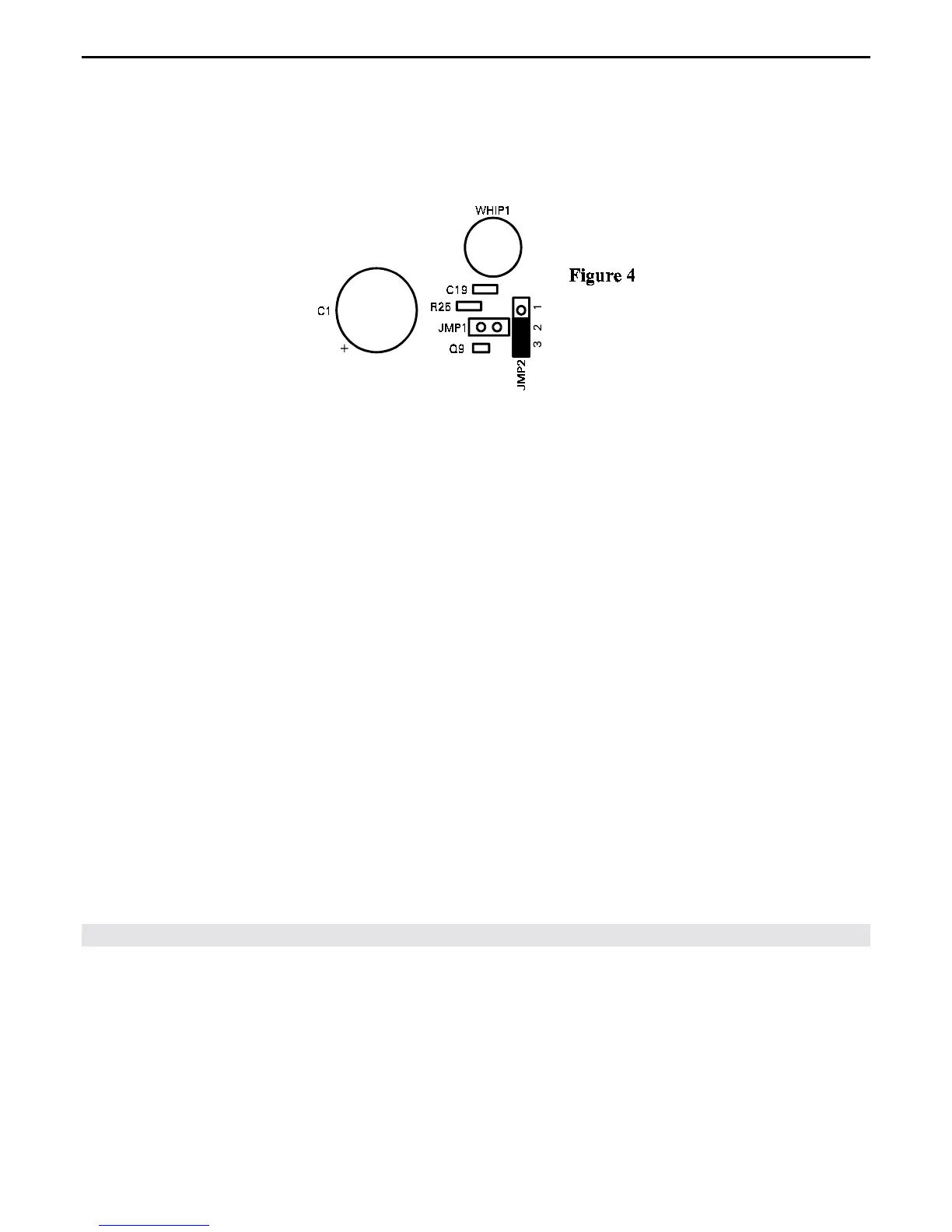
For moderate sensitivity, JMP2 must be activated. To activate JMP2 remove the shorting clip from
previous position and place it across pins 2 and 3 of JMP2 (see Figure 4).
When the pre-amp is used with the external antenna (Figure 3 & 4) we recommend removing the internal
telescoping antenna (WHIP) to ensure reception isn't compromised.
Installing the MFJ-1026
Please read the following section carefully.
The best location for this unit is at the operating position next to or above the transceiver or receiver.
The MFJ-1026 controls must be adjusted during normal operation while listening to the receiver or
watching the receiver's S meter. For most installations, connect the MFJ-1026 as follows:
1. Connect the MFJ-1026 "RADIO" connector to the transceiver or receiver's antenna terminal with a
short coaxial jumper cable.
2. Connect the lead that used to go to the transceiver or receiver's antenna terminal to the MFJ-1026
connector labeled "MAIN ANTENNA".
3. Connect the noise or auxiliary antenna to the MFJ-1026 connector labeled "AUXILIARY
ANTENNA", or use the internal telescoping whip.
4. Connect a two-conductor shielded cable between the T/R Control connector and an external PTT
source. Many modern transceivers have an EXTERNAL PTT output pin on one of the radio
accessory ports. This can be used to pull the T/R Control line LOW, so the MFJ-1026 is put safely
into the transmit mode, before any signal is transmitted.
 Loading...