12. Level Meter: You can see the output level of the MFJ-299 with this meter. Adjustments should be
made as mentioned in #4 & #11above so that the output level does not exceed 0dB. If the output level
exceeds 0dB, distortion will occur.
13. Battery Cover: Remove the screws on the bottom plate. Install a fresh 9V battery (not included) to the
connector. Replace the battery cover and screws before operation.
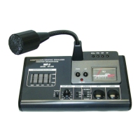
Microphone Output Connector Information
A
for ICOM Transceivers
B
for Kenwood Transceivers
C
for Yaesu Transceivers
1 No Connection 1 Frequency UP 1 No Connection
2 PTT Ground 2 +8V DC Input 2 No Connection
3 Microphone Input 3 PTT Ground 3 PTT
4 Microphone Ground 4 PTT 4 Microphone Input
5 PTT 5 Microphone Ground 5 Ground
6 No Connection 6 Microphone Input 6 +8V DC Input
7 Frequency UP/DOWN 7 No Connection 7 Frequency UP
8 +8V DC Input 8 Frequency DOWN 8 Frequency DOWN
The compressor amplifier serves to keep distortion low and the output level constant regardless of the input
level. The audio input level is automatically adjusted by an electrical volume control. Please refer to the sketch
above. The input level from A to B is linearly amplified. The input level from B to D is compressed. The
compression level is the voltage ration of input levels at B and D. The high compression level has a 45 dB
minimum compression level. You can extend the communication distance by using the rated output power of
your transceiver and microphone.
 Loading...