EasyManua.ls Logo

MFJ MFJ-299 User Manual

MFJ MFJ-299
4 pages
To Next Page IconTo Next Page
Page #1 background imageLoading...
Page #1 background image
MFJ-299
Deluxe Desktop Microphone / Ham Station Console
Thank you very much for your purchase of the MFJ-299 Deluxe Desktop Microphone / Ham Station Console.
To enjoy this unit to full satisfaction, please read the instructions carefully.
SPECIFICATIONS
Microphone High Sensitivity Ceramic Microphone Element
Compressor Level High: 45dB, Med: 30dB, Low:10 dB
S/N Ratio (Graphic Equalizer) 80 dB
Distortion Factor 0.05% (at flat)
Graphic Equalizer 4 Elements (270, 540, 1000, & 2000 Hz)+12dB range
Output Voltage COMP: 0 – 30 mV (RMS)
Matching Output Impedance 500 ohms – 100K ohms
Power Voltage DC 6~9 V
Current Consumption (EQ off) Receive – 3.5 mA, Transmit – 4.5 mA
(EQ on) Receive – 10 mA, Transmit – 11 mA
Alarm Sound Approximately 4.5 kHz Intermittent Tone
Size 8.937(W) X 5.118 (D) X 12.598 (H) inches
Weight 2.2 Lbs.
FEATURES
1. High Sensitivity Ceramic Microphone Element.
2. High Quality Compressor Amplifier. For constant transmission at an optimum level without distortion
regardless of audio input.
3. Equipped with Graphic Equalizer for Optimum Audio Output Quality. The 4 Element Graphic
Equalizer with center frequencies of 270, 540, 1000, and 2000 Hz can control the audio output quality.
It gives the best audio quality for FM and maximum efficiency for SSB and DX.
4. Triple input socket for most transceiver models.
5. Battery check circuit built in. Press the power switch and the level meter indicates the battery
condition with power voltages for a few seconds.
INSTALLATION
1. Install a fresh 9V battery (not included) in the battery compartment.
2. The MFJ-299 must be used with one of the following cables (sold separately):
MFJ-5397I - compatible with most ICOM transceivers that have an 8-Pin round connector.
MFJ-5397K - compatible with most Kenwood transceivers that have an 8-Pin round
connector.
MFJ-5399Y - compatible with most Yaesu transceivers that have an 8-Pin round connector.
MFJ-5397MX - compatible with most transceivers that have an 8-Pin modular connector.
3. Plug the cable into the Microphone Output Connector and set the Microphone Output Connector
Switch as follows:
Position A for all ICOM transceivers.
Position B for all Kenwood and Yaesu FT-100 transceivers.
Position C for all Yaesu transceivers (except FT-100).
CAUTION:
Please be sure to use MFJ conversion cables. The MFJ-5399 is compatible with most transceivers that
have an 8-Pin round connector. The MFJ-5399M is compatible with most transceivers that have an 8-
Pin modular connector.
Please be careful about high SWR of antenna and incomplete grounding. This may cause RF Feedback
and noise depending on coaxial cable layout.
Please be sure to turn the power switch off after use to ensure long battery life.
Do not subject the microphone in high temperatures or place in direct sunlight.
Question and Answer IconNeed help?

Do you have a question about the MFJ MFJ-299 and is the answer not in the manual?

MFJ MFJ-299 Specifications

General IconGeneral
TypeDynamic
Frequency Response50 Hz - 15 kHz
ConnectorXLR
Polar PatternCardioid
Sensitivity-75 dB

Summary

Product Features

High Sensitivity Ceramic Microphone

Describes the high sensitivity ceramic microphone element used in the device.

Compressor Amplifier

Details the high-quality compressor amplifier for constant transmission at optimum levels.

Graphic Equalizer for Audio Quality

Highlights the 4-element graphic equalizer for optimizing audio output quality and efficiency.

Transceiver Connectivity

Notes the triple input socket for compatibility with various transceiver models.

Battery Status Indicator

Explains the built-in battery check circuit that indicates power condition.

Device Installation

Initial Battery Setup

Instructions for installing a fresh 9V battery in the battery compartment.

Connecting Transceivers

Guidance on connecting the MFJ-299 using specific MFJ conversion cables.

Microphone Output Connector Switch

Details on setting the output connector switch based on transceiver type.

Controls and Operation

Power and Equalizer Switch

Describes the ON/OFF switch for power and graphic equalizer functions.

Compressor Level Settings

Explains the HIGH, MED, and LOW settings for the compressor level.

Transmit Indicators and Buttons

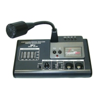
Details the 'On Air' indicator, PTT, and LOCK switches for transmission.

Audio Output and Frequency Adjustments

Covers the Output Level Volume, UP/DOWN switches, and Function Keys.

Microphone Connector and Equalizer

Information on the output connector, switch, and graphic equalizer adjustment.

Level Meter and Battery Cover

Guidance on using the level meter and accessing the battery compartment.

Microphone Output Connector Pinouts

Detailed pinout information for microphone output connectors (A, B, C).

Compressor Functionality

Explanation of the compressor amplifier's characteristic curve and operation.

Limited Warranty Information

Warranty Coverage and Terms

Outlines the 12-month limited warranty terms, proof-of-purchase, and service procedures.