MFJ-434B Instruction Manual Voice Keyer
5
IMPORTANT WARNING: The MFJ-434B's internal jumpers are factory set for
compatibility with Yaesu transceivers (FT-817, FT-857, FT-897) using conventional
dynamic or crystal microphones. When using Icom or Kenwood/Alinco products,
internal jumpers must be reset for the correct manufacturer and microphone voltage.
Microphone Jumper Configuration (Icom, Kenwood, Yaesu)
1. Disconnect any 12VDC source from the MFJ-434B.
2. Next remove the screws from the sides and top of the voice keyer enclosure. Remove the
cover, being carful not to stress the monitor speaker wires.
3. Use Appendix A at the end of this manual to locate the jumper configuration specific to
your Icom, Kenwood, or Yaesu radio. If your radio is not included in the appendix use
the section below titled Microphone Jumper Configurations (Other Radios).
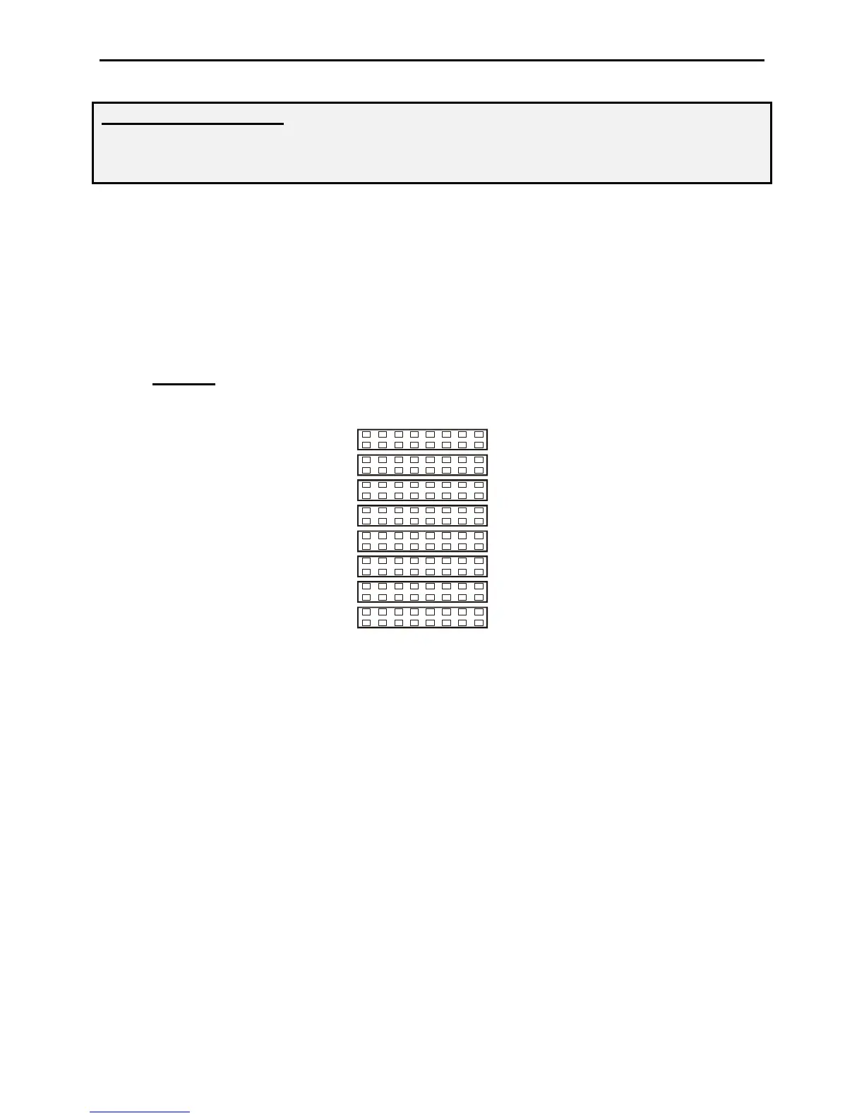
4. JMP2-9:
On the left side of the circuit board, locate the set of headers JMP2-9. There
are 8 possible configurations on each row of jumpers 2-9. See the jumper diagram below.
JMP 8
JMP 9
JMP 7
JMP 3
JMP 4
JMP 6
JMP 5
1
4
3
6
7
JMP 2
Mic
Mic
Mic Gnd
Mic Gnd
PTT
PTT
PTT Gnd
Direct
5. Remove the jumpers on JMP2-9 ONLY.
6. Replace the jumpers on JMP2-9 using the diagram specific to your radio located in the
Appendix of this manual. If your radio is not listed use the following section for
determining the jumper settings for other radios.
7. Replace the cover and screws when you have completed the configuration.
Microphone Jumper Configuration (Other Radios)
1. If your radio is not included in the appendix, the MFJ-434B can be configured by
obtaining a copy of the wiring diagram specific to your radio microphone.
2. Use the microphone wiring diagram to determine which microphone pins are used for
PTT, PTT Gnd, Mic, Mic Gnd. The front panel view of the microphone connectors
below can be used to determine how the pins will need to be configured.
 Loading...