POWER SOURCE: 12 15 V @ 2A (+) TO CENTER PIN
The MFJ 4114 ac/dc PORTABLE POWER PACK and MFJ 4110 ac WALL ADAPTER SUPPLY are
especially designed for your radio. However, you may use any filtered dc power source capable of delivering
12 15 volts at 2 Amps (13.8V required for full RF output). The dc power connector at the rear of your MFJ
9420 is a 5.5mm OD,2.1mm ID coaxial type jack. Extra plugs are available from Radio Shack stores (#274
1567). Always connect plus (+) to the CENTER PIN.
MICROPHONE: USE 600 OHM DYNAMIC
The MFJ 9420 speech circuit is designed especially for a 600 Ohm dynamic microphones such as the MFJ
290 (the MFJ 290 is supplied if you purchase the MFJ 9420M package). You may also use other suitable
600 Ohm desk or hand mics by installing a 5 pin DIN plug (Radio Shack #274 003). See installation
diagram below:
PTT pin 3
MIC pin 4
GND pins 1,2,5.
WARNING:
NEVER USE AN AMPLIFIED MICROPHONE WITH YOUR TRANSCEIVER. The speech processor
already has extremely high gain and may distort severely if overdriven by a "power mike".
ANTENNA REQUIREMENTS: VSWR 3:1 OR LESS
The MFJ 9420 accepts most 20 Meter antennas with a VSWR of 3:1 or less. Use your regular station
antenna or a portable 20 Meter dipole such as the MFJ 1772 ultra light. For non resonant wires, use a tuner
such as the MFJ 971. Always "rough tune" for maximum receiver sensitivity first using incoming signals
and your S Meter to find a peak. AVOID OPERATING INTO UNMATCHED HIGH VSWR ANTENNAS.
THE MFJ 9420 DOES NOT HAVE A HIGH VSWR SHUT DOWN CIRCUIT AND BADLY
MISMATCHED LOADS COULD RESULT IN TRANSMITTER
INSTABILITY AND GENERATION OF OUT OF BAND SIGNALS!
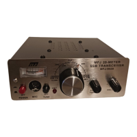
TRANSCEIVER:
STEP 1. Connect a suitable microphone, power source, and 20 Meter antenna.
STEP 2. Turn VOLUME fully counter clockwise (down) and press ON switch to power up radio. PWR
indicator should light.
STEP 3. Turn VOLUME clockwise for a comfortable listening level.
STEP 4. If you are using an antenna tuner, adjust ATU controls for strongest received signals or maximum
background noise on the S meter. Then, press CARRIER to generate a steady RF signal for final
adjustment. Red XMIT indicator should light.
STEP 5. The VFO tuning range covers 14.150 14.350 MHz and the MFJ 9420 tuning dial was carefully
calibrated at the factory. However, it is by nature an analog frequency readout that may be subject to some
inaccuracy or misinterpretation. To ensure compliance with FCC rules, we suggest the following:
 Loading...