Do you have a question about the MFZ Ovitor CS 110 and is the answer not in the manual?
Explains the meaning of safety and reference symbols used in the manual.
Safety notice indicating a danger that will directly result in death or severe injury.
States warranty validity and liability exclusions for improper use or parts.
Defines intended use and specifies qualified personnel for installation/servicing.
Guidelines for electrical works, power disconnection, and cable routing.
Lists essential regulations and standards for connecting and servicing the unit.
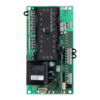
Lists CS 110 control unit models and available housing options.
Outlines the general conditions required for proper system function.
Provides detailed circuit diagrams for connecting the unit to the mains power supply.
Details connection procedures for both 3-phase and 1-phase door operators.
Explains how to connect mechanical and electronic limit switches to the system.
Details the connection of safety devices like emergency stop or door safety circuits.
Covers the connection of various command devices like button units and key switches.
Illustrates the connection terminal for the relay output.
Emphasizes the necessity of the plug-in module for operation.
Explains the function of the operating mode selector switch.
Introduces optional modules like radio receivers and shut-off systems.
Guides on setting OPEN and CLOSE travel limits using circuit board buttons.
Explains setting travel limits using the CSI 3-button input unit.
Guides on setting travel limits via the LCD display interface.
Refers to the manual for setting mechanical travel limits.
Provides a diagram and key for the LCD monitor interface.
Describes the four operating modes: AUTOMATIC, ADJUSTMENT, INPUT, DIAGNOSTICS.
| Brand | MFZ Ovitor |
|---|---|
| Model | CS 110 |
| Category | Door Opening System |
| Language | English |