Do you have a question about the MFZ Ovitor FS 345 and is the answer not in the manual?
Guidelines on reproduction, alterations, dimensions, and illustrations.
Explains safety symbols like Danger, Warning, Caution, Notice, Check, and Reference.
Covers operation safety, target group, installation, and relevant regulations.
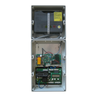
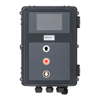
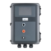
Details FS 345 control components, emergency power, models, and housing.
Ensures operational readiness and correct mains voltage/rotation field.
Describes connecting the FS 101 board, battery, and microprocessor.
Schematic showing mains power and motor connection.
Wiring diagrams for 230V AC single and three-phase mains connections.
Details terminal assignments for command and safety devices.
Wiring examples for various button and key switch setups.
Wiring for closing edge devices and photoelectric barriers.
Diagram of FS 101 board, battery, and key to its terminals.
Explains DIP switch settings for operator types and fire alarm.
Configuration details for FT and FD operator types.
Details connections for relays, motor, fire alarm, and limit switches.
Wiring examples for normally closed and open fire alarm contacts.
Explains relays for operation/error, command, and safety edge status.
Details connection for limit switches and their analysis by FS101.
Instructions for setting limit switches and warnings about incorrect adjustment.
Instructions for setting limit switches on FT operators.
Identifies monitor elements and describes the four operating modes.
Explains the function and usage of each operating mode.
Illustrates navigating menus, setting values, and scrolling through options.
Details how to scroll menus and check system status in DIAGNOSIS mode.
Describes display states in automatic mode (OPEN, CLOSE, STANDBY, PART OPEN).
Lists functions like language, RUNTIME, OPEN TIME, and their configurable parameters.
Details parameter functions and their settings.
Lists display indicators, their meanings, and statuses in diagnosis mode.
Explains LED codes (D01-D08) and their associated error diagnoses.
Details LED status and error diagnoses for various functions.
Explains error/status codes for the red diagnostic LED D019.
Lists fault messages, causes, and rectification steps for system errors.
How to set TIME 1 for door closing delay after mains failure.
Monitoring emergency operation with a contact bar and SKS function.
Procedure for closing the door via operator when fire alarm is active.
Time-controlled function for tight door closure in emergency mode.
Describes buzzer signals for emergency operation and battery status.
Procedure to check battery condition and emergency function via TEST button.
How the control prevents battery deep discharge when power is absent.
Automatic testing of battery condition by checking voltage.
Guidelines for recharging maintenance-free batteries, including temperature.
Warnings about improper use of the charging device and warranty.
Wiring diagram for motor brake connection on FT operators.
Wiring diagram for auxiliary motor connection on FDF 60 operator.
Lists housing dimensions, supply voltage, power, and environmental specs.
States control is maintenance-free but details safety for electrical work.
Declares conformity with EU directives and lists applied standards.
| Brand | MFZ Ovitor |
|---|---|
| Model | FS 345 |
| Category | Control Systems |
| Language | English |