Do you have a question about the MFZ Ovitor Control CS 310 and is the answer not in the manual?
Highlights life-threatening danger from non-compliance with documentation.
Provides instructions for safe installation, including disconnection from electricity and local regulations.
Essential safety precautions for installation to prevent electric shock and property damage.
Warns about potential property damage due to improper installation of the controller.
Details preconditions for proper function, including voltage, phase, and circuit breaker requirements.
Warns about the danger of injury from uncontrolled door movement when using command devices.
Warns about potential damage to the circuit board due to incorrect input connections.
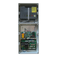
Diagram and description of the four potential-free relay outputs.
Details on connecting the LCD monitor and warnings about improper installation.
Information on connecting ES, I/O, and GV modules via MS BUS.
Procedure to check and change the door's direction of rotation and travel.
Instructions for setting mechanical limit switches, referencing separate documentation.
Guide to setting OPEN/CLOSED end positions using the circuit board buttons.
Warns about potential damage during LCD monitor installation and end position setting.
Introduction to the LCD monitor, its keys, and installation warnings.
Describes the four operating modes: AUTOMATIC, ADJUSTMENT, INPUT, and DIAGNOSIS.
Details on INPUT mode for parameter alteration and DIAGNOSIS mode for checks.
Explains how to activate the Expert Menu to access all input parameters.
Explains the RESET function for returning parameters to factory settings and different reset types.
Step-by-step procedure for resetting the control using the LCD monitor.
Procedure for resetting the control without an LCD monitor using circuit board buttons.
Details the various display messages and their meanings in Automatic Operating Mode.
Details relay modes for traffic light indicators in different door states.
Explains relay modes that indicate door position status.
Describes the functionality of Input 1 for MOD1 through MOD8.
Describes the functionality of Input 1 for MOD9 through MOD30.
Describes the functionality of Input 2 for OFF and MOD2 through MOD7.
Lists LCD error messages and their rectifications for system response, direction, and safety circuits.
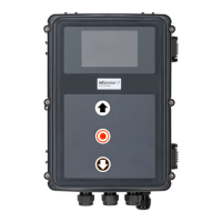
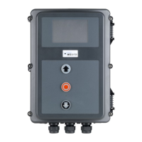
Provides specifications for housing dimensions, installation, power, inputs, outputs, and environmental factors.
Details compliance with EN ISO 13849-1 for safety functions like Emergency Stop and Stop Circuit.
Crucial warnings regarding electric shock and property damage during maintenance.
| Brand | MFZ Ovitor |
|---|---|
| Model | Control CS 310 |
| Category | Control Systems |
| Language | English |