6 – Control CS 310 / Rev.I 1.55 Control CS 310 / Rev.I 1.55 – 7
5. Installation
5.1 5.1 Safety instructions for installationSafety instructions for installation
WARNING!
Life-threatening danger due to electric shock!
Before performing wiring work, always disconnect the
Before performing wiring work, always disconnect the
system from the power supply. Make sure that the power
system from the power supply. Make sure that the power
supply remains disconnected during wiring work.
supply remains disconnected during wiring work.
Property damage due to improper installation of
the controller!
In order to avoid damage to the controller, observe the
following points:
− Onlyqualiedandtrainedelectriciansmayworkon
electrical systems.
− Switch off the power supply to the system, check that it
is de-energised and safeguard against reconnection.
− Mains cables and control cables must be routed separa-
tely.
− The line types and cross-sections must be selected in
accordancewiththevalidspecications.
− It is essential to observe the local protective regulations.
− Observethespecicationsofthedoormanufacturerfor
installation.
To guarantee that the equipment functions properly, it must
be ensured that:
− The door is installed, fully functional and designed for
power-driven operation.
− Thegearmotoristtedandreadyforoperation.
− The command and safety devices are installed and ready for
operation.
− The control housing with the CS 310 control is installed.
The relevant manufacturers’ instructions must be adhered
to for the installation of the door, the MFZ motor, and the
command and safety devices.
5.2 5.2 Mains connectionMains connection
Preconditions
To guarantee that the controls function properly, the following
points must be ensured:
− The mains voltage must correspond to the voltage stated
on the type plate.
− The mains voltage must be the same as the voltage of the
operator.
− Forthree-phasecurrent,aclockwiserotatingeldis
required.
− For a permanent connection, an all-pole main switch must
be used.
− For a three-phase connection, only 3-way automatic circuit
breakers Typ C (10 A) may be used.
Malfunctions can occur as a result of incorrect
installation of the control!
Beforeswitchingonthecontrolforthersttime,acheck
must be carried out after completing the wiring to ensure
that all the motor connections at the motor and at the
controlissecurelyxed.Allcontrolvoltageinputsare
galvanically isolated from the supply.
The control and load lines of the connected motors must be
double-insulated along their entire route.
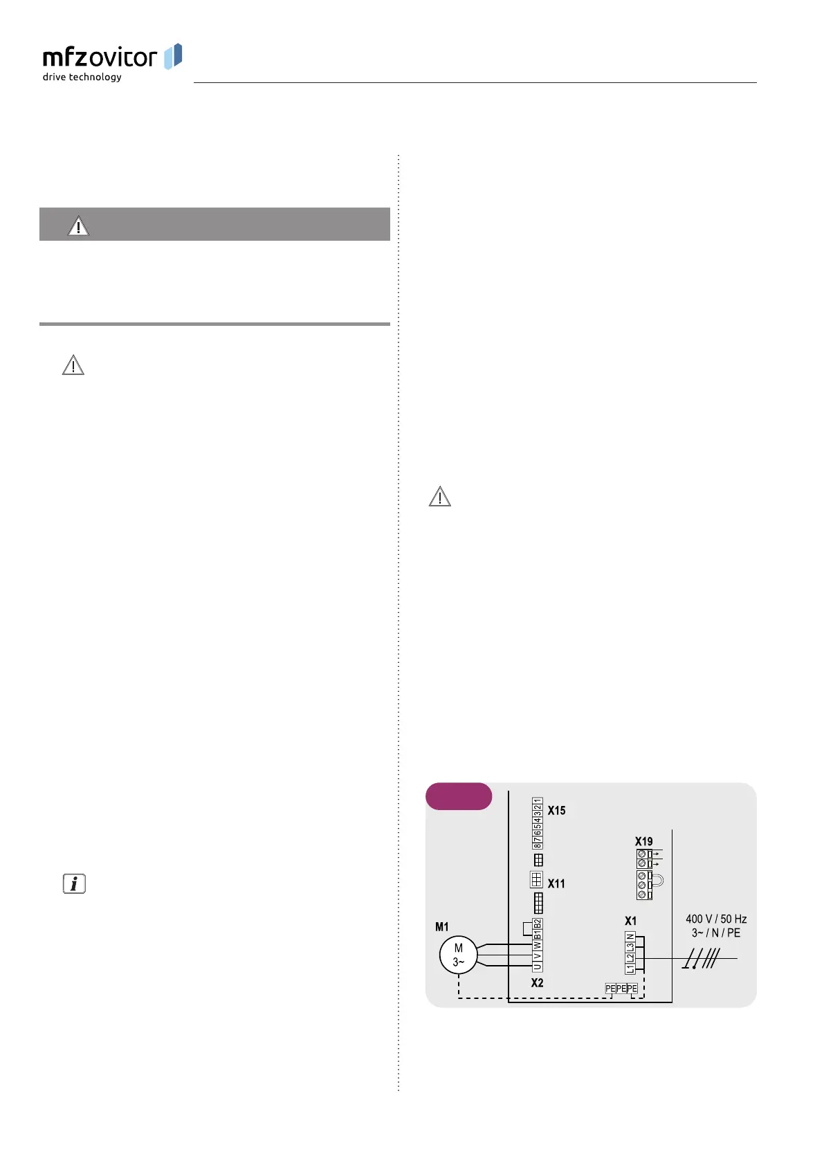
Detailed circuit diagram for mains connection and
motor connection (400 V / three phase)
N
L
5.2 / 1