8 – Control CS 310 / Rev.I 1.55 Control CS 310 / Rev.I 1.55 – 9
EN
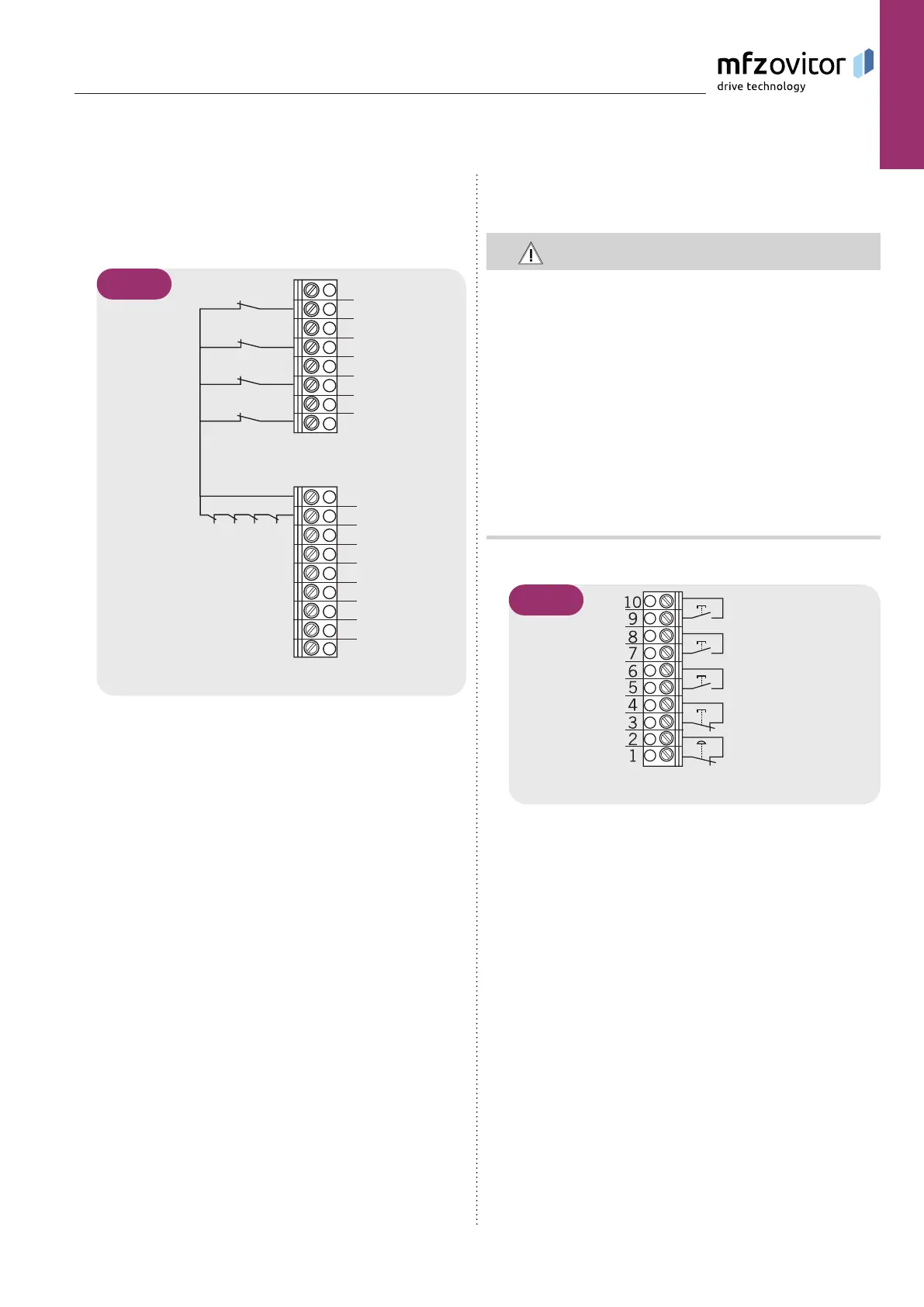
Connection example for solution with 6 leads
Terminal blocks X11 and X2
1
2
3
4
5
6
7
8
S3
S4
S7
S8
S2
S5
S1
S6
U
V
W
B1
B2
5.5 / 4
S1 Additional limit switch, OPEN
S2 Limit switch, OPEN
S3 Safety limit switch, OPEN
S4 Safety limit switch, CLOSED
S5 Limit switch, CLOSED
S6 Additional limit switch, CLOSED
S7 Thermal overload protection for motor
S8 Emergency operation (n.c. contact)
The end position system will be recognised automatically
by the control during initial use and following a RESET. If
a change is made at a later date, the relevant end position
system must be selected via a parameter setting in INPUT
mode.
➔ “10.2 Input operating mode“
5.6 5.6 Connection of command devicesConnection of command devices
CAUTION!
Danger of injury due to uncontrolled movement of
the door!
A CLOSE command in dead-man operation without a view
of the door is not permitted.
Install command devices for deadman operation in direct
Install command devices for deadman operation in direct
sight of the gate, but outside the danger area for the user.
sight of the gate, but outside the danger area for the user.
A CLOSE command without visual sight of the door may
A CLOSE command without visual sight of the door may
only be given via input 1 / MOD32 (X4 / 9-10).
only be given via input 1 / MOD32 (X4 / 9-10).
If the command device is not a key switch:
Install it at a height of at least 1.5 m off the ground.
Install it at a height of at least 1.5 m off the ground.
Install it so as to make it inaccessible to the general
Install it so as to make it inaccessible to the general
public.
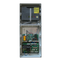
Command devices (standard)
X3
A
B
C
D
E
5.6 / 1
Legend :
A Button / DOWN input
B Button / pulse input
C Button / UP input (UP inside, with active two-way
control)
D STOP button
E Emergency stop command device