4 – Control CS 310 / Rev.I 1.55 Control CS 310 / Rev.I 1.55 – 5
EN
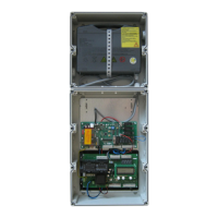
4.3 4.3 Motherboard CS 310 Motherboard CS 310
(with plugged-in LCD monitor)(with plugged-in LCD monitor)
Key:
X1: Terminal block for mains connection
X2: Terminal block for motor
X3: Terminal block for command devices
X4: Terminal block for safety elements
X5: Terminal block for relay
X6: Sockets for internal ON-OFF switch
X7: Sockets for internal 3-button input unit KDT
X8: Sockets for LCD monitor
(under the LCD monitor)
X9: Sockets for radio receiver
X10: Sockets for weekly timer
X11: Sockets for digital end position system
X12: Sockets for external radio receiver
X13: Connector strip for internal 3-fold button CS
X14: Interface RS 485
X15: Terminal block for mechanical end position system
X16: Sockets for BUS system (MS BUS)
X17: Sockets for BUS system (MS BUS)
X18: Frequency converter interface
X19: Power supply for external devices
230V / 50 Hz protected by F1 (1 A delay) fuse
X20: Sockets for transmission system
H4: operational readiness
Lights up when power supply available.
H6: Status message
Lights up when the safety devices are actuated or if
an error occurs
S1: Programming button (+)
(under the LCD monitor)
S2: Programming button (-)
(under the LCD monitor)
S3: Programming button (P)
(under the LCD monitor)
X11
X14
X18
B2
B1
W
V
X2
U
1
2
3
4
5
6
7
8
X5
1
2
3
4
5
6
7
8
X15
X10
1
2
3
4
5
6
7
8
9
10
X4
X3
X7
X6
X12
PE
PE
PE
N
L3
L2
L1
X1
1
2
3
4
5
6
7
8
9
12
11
10
X8
S3
S2
S1
X9
X20
H6
X13
X19
F1
X16
X17
H4
N
L
X19
N
L
X19
400 V
230 V
4.3 / 1
A
B
B
A Output: 230 V.
Power supply for external devices.
No power line entry for the control unit itself.
➔ “5.3 Power supply for external devices“
B The position of the jumper must take into account the
power supply voltage and the motor voltage.