6 – Control CS 310 / Rev.I 1.55 Control CS 310 / Rev.I 1.55 – 7
EN
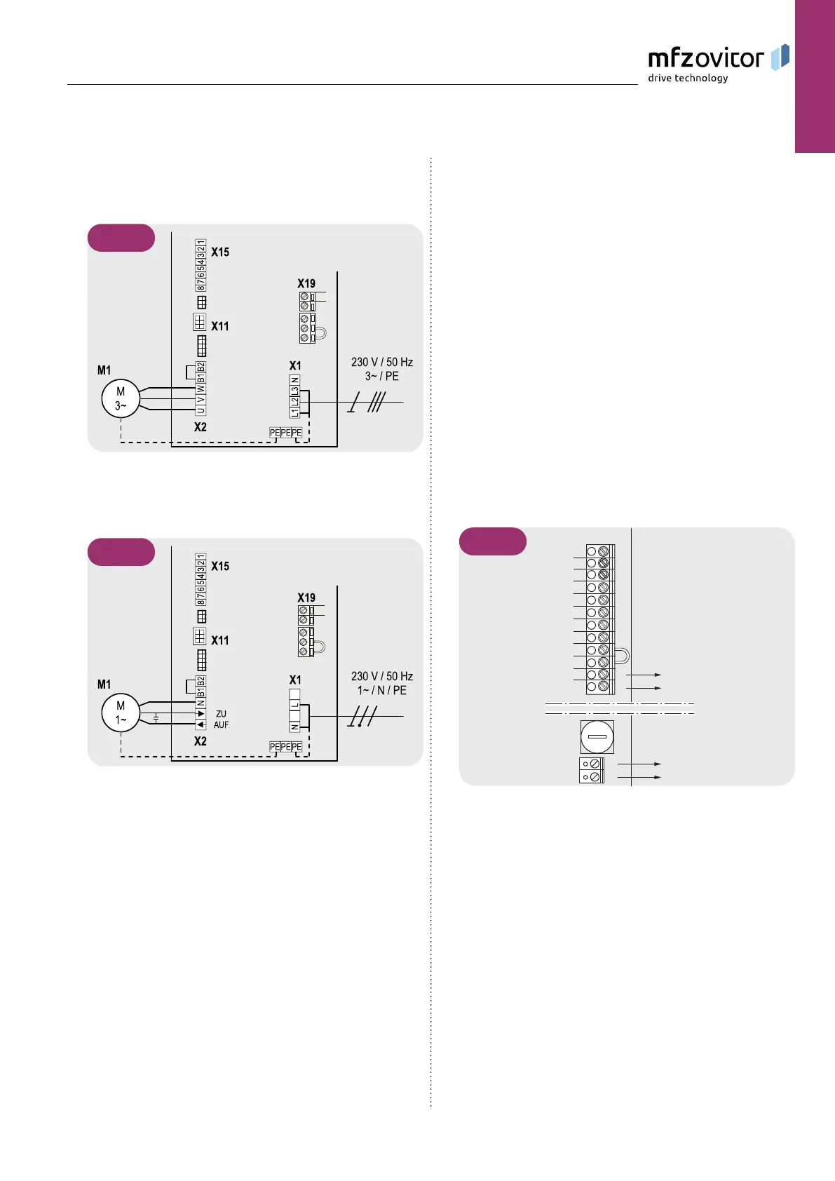
Detailed circuit diagram for mains connection and
motor connection (230 V / three phase)
5.2 / 2
Detailed circuit diagram for mains connection and
motor connection (230 V / single phase)
5.2 / 3
Key:
M1: Motor
X1: Terminal block for mains connection
X2: Terminal block for motor
X11: Sockets for digital end position system with safety
circuit
X15: Terminal block for mechanical limit switches
(Safety circuit at X2 / B1-B2)
X19: Power supply connection for external devices
Connection:
Connect the digital end position system or mechanical limit Connect the digital end position system or mechanical limit
switches to the control.switches to the control.
Connect the control to the motor.Connect the control to the motor.
Connect the control to the mains power supply.Connect the control to the mains power supply.
Cable groups must be secured close to their relevant Cable groups must be secured close to their relevant
terminals using a cable tie. terminals using a cable tie.
➔ “12.Technicaldata“onpage48
5.3 5.3 Power supply for external devices Power supply for external devices
The CS 310 has 2 separate voltage supplies for external com-
ponents, such as signal devices, light barriers, etc.
X19 230V/1~
X4 24V-DC
X19
max. 1A
230V-AC
max. 500mA
24V-DC
1
2
3
4
5
6
7
8
9
12
11
10
F1
-
+
L
N
5.3 / 1
NOTICE:
Use of the connection X19 is only possible with a supply with
400V / N / 3~.
The connection X19 is protected by the fuse element F1 (max.
1 A / T).