12 – Control CS 310 / Rev.I 1.55 Control CS 310 / Rev.I 1.55 – 13
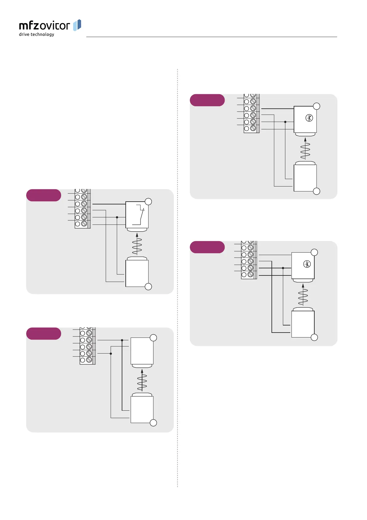
5.8 Photocell connection 1
The photocell system will be recognised and programmed
automatically during initial operation and following a RESET.
If a photocell system is not connected, the input will be
queried every time the power supply is switched on again,
until a closing edge safety device is recognised. If a change is
made at a later date, the relevant system must be selected via
a parameter setting in INPUT mode.
➔ “10.2 Input operating mode“
Photocell NC
Parameter LIGHT BARR. 1 = MOD 2
OUT
-
+
-
+
NC
1
2
3
4
5
X4
R
T
5.8 / 1
MFZ two-wire photocell
Parameter LIGHT BARR. 1 = MOD 1
2
1
2
1
1
2
3
4
5
X4
R
T
5.8 / 2
Three-wire NPN photocell
Parameter LIGHT BARR. 1 = MOD 2
OUT
-
+
-
+
NPN
1
2
3
4
5
X4
R
T
5.8 / 3
Three-wire PNP photocell
Parameter LIGHT BARR. 1 = MOD 3
OUT
-
+
-
+
PNP
1
2
3
4
5
X4
R
T
5.8 / 4
Legend:
R Receiver
T Transmitter
NOTICE:
All photocells are active for the OPENING or CLOSING
direction, depending on the setting.
➔ “10.2 Input operating mode“ (Parameter LB FUNC. 1)
Installation