20 – Control CS 310 / Rev.I 1.55 Control CS 310 / Rev.I 1.55 – 21
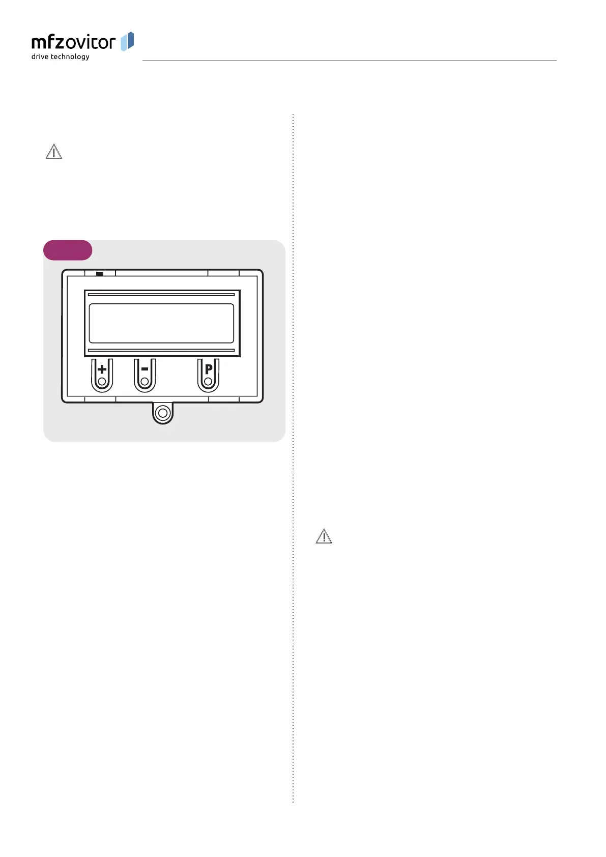
8.1 8.1 Overview of the LCD monitorOverview of the LCD monitor
Damage can occur through improper installation!
The mains power supply must be switched off before
connecting the display unit. Only an MFZ display unit
(article number 91447) may be used.
A
B
C D E
F
G
H
8.1 / 1
AUTOMATIC O
STANDBY
Key:
A: Mode of operation / Diagnostics info
B: Parameters / Diagnostics info
C: Button (+)
D: Button (–)
E: Button (P)
F: Value / Status
G: Value / Status
H: Jumper
If jumper H is removed, the (+) button, the (–) button and the
(P) button have no function.
The display still functions.
After the control has been switched on, it will be in the
initialisation phase and “PLEASE WAIT ...” will appear in
the display. The control system is not ready for use. After
switchingonforthersttime,theinitialisationphasetakes
approximately 60 seconds.
8.2 8.2 LCD monitor, modes of operationLCD monitor, modes of operation
The control has four modes of operation with the LCD
monitor:
1. AUTOMATIC
2. ADJUSTMENT
3. INPUT
4. DIAGNOSIS
ADJUSTMENT, INPUT and DIAGNOSIS modes are exited
automatically 7 seconds after the last button was pressed.
The control then goes into AUTOMATIC mode.
Operating mode 1: AUTOMATIC
The door/gate system is operated in the AUTOMATIC
operating mode.
Display:
− Displays the action being carried out
− Displays any error messages
If the “PRESS/REL” parameter is set to MOD2–6 in the input
menu, the display changes from AUTOMATIC to MANUAL.
Operating mode 2: ADJUSTMENT
ADJUSTMENT mode is used for setting the OPEN/CLOSED
end positions.
Malfunctions can occur as a result of incorrect
operation of the control!
In ADJUSTMENT mode, the door will not stop automatically
when it reaches the end position if an electronic end
position system (AWG) is used. The door can be damaged if
driven beyond the end position.
Fine adjustments can be made in the INPUT operating mode.
Display:
− The current end position value is shown
8. Programming