EasyManuals Logo

MFZ Ovitor Control CS 310 User Manual

MFZ Ovitor Control CS 310
56 pages
To Next Page IconTo Next Page
To Previous Page IconTo Previous Page
Page #54 background imageLoading...
Page #54 background image
54 – Control CS 310 / Rev.I 1.55
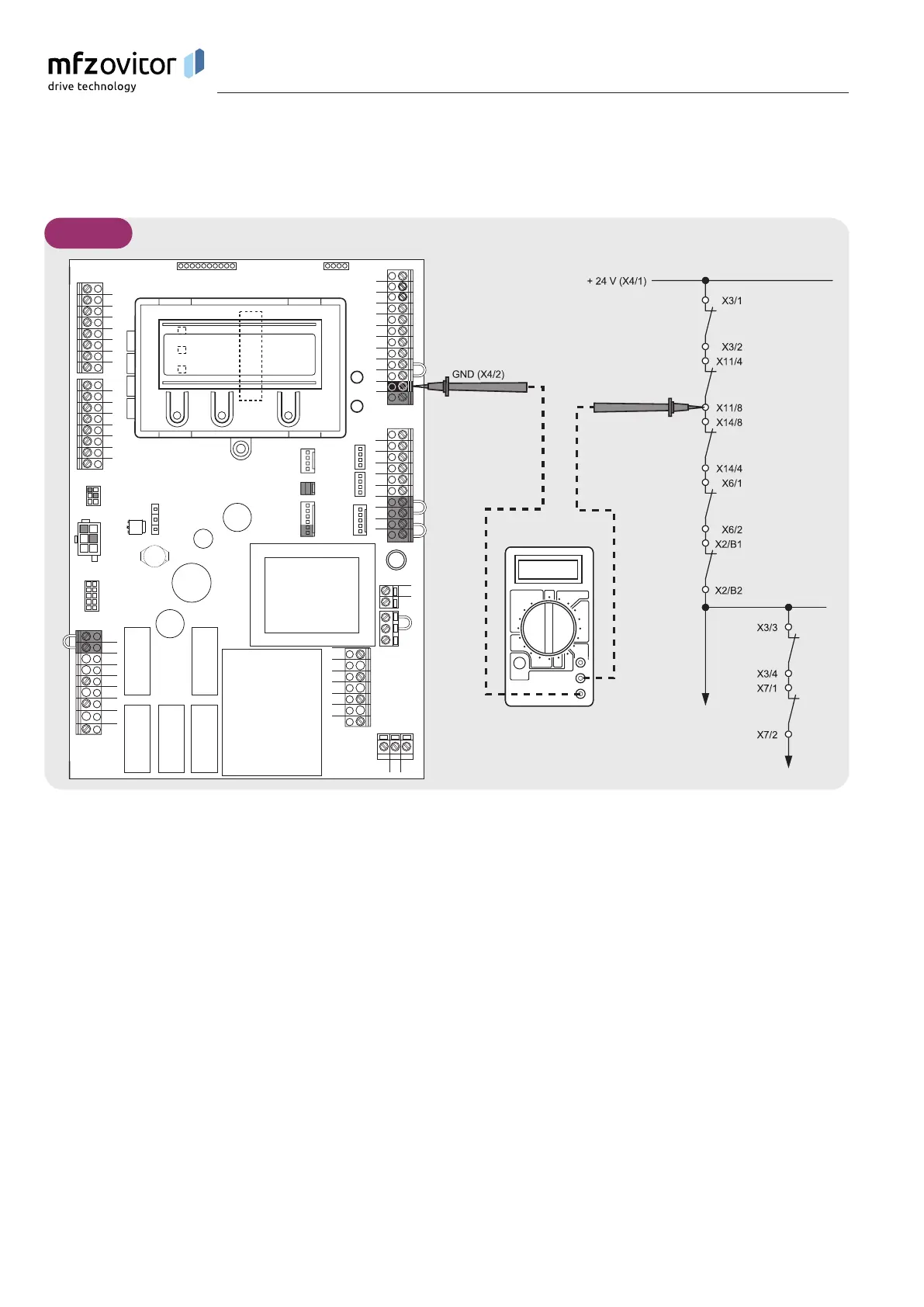
15.2 15.2 Measuring points, safety circuitMeasuring points, safety circuit
Appendix
X11
X14
X18
B2
B1
W
V
X2
U
1
2
3
4
5
6
7
8
X5
1
2
3
4
5
6
7
8
X15
X10
1
2
3
4
5
6
7
8
9
10
X4
X3
X7
X6
X12
PE
PE
PE
N
L3
L2
L1
X1
1
2
3
4
5
6
7
8
9
12
11
10
X8
S3
S2
S1
X9
X20
H6
X13
X19
F1
X16
X17
H4
N
L
A
B
15.2 / 1
NOTICE:
The measurement range must be set for 24 V-DC.
A Emergency Stop
B Stop
Measure at all measuring points on the diagram in order to Measure at all measuring points on the diagram in order to
locate the interruption.locate the interruption.

Table of Contents

Questions and Answers:

Question and Answer IconNeed help?

Do you have a question about the MFZ Ovitor Control CS 310 and is the answer not in the manual?

MFZ Ovitor Control CS 310 Specifications

General IconGeneral
BrandMFZ Ovitor
ModelControl CS 310
CategoryControl Systems
LanguageEnglish

Related product manuals