16 – Control CS 310 / Rev.I 1.55 Control CS 310 / Rev.I 1.55 – 17
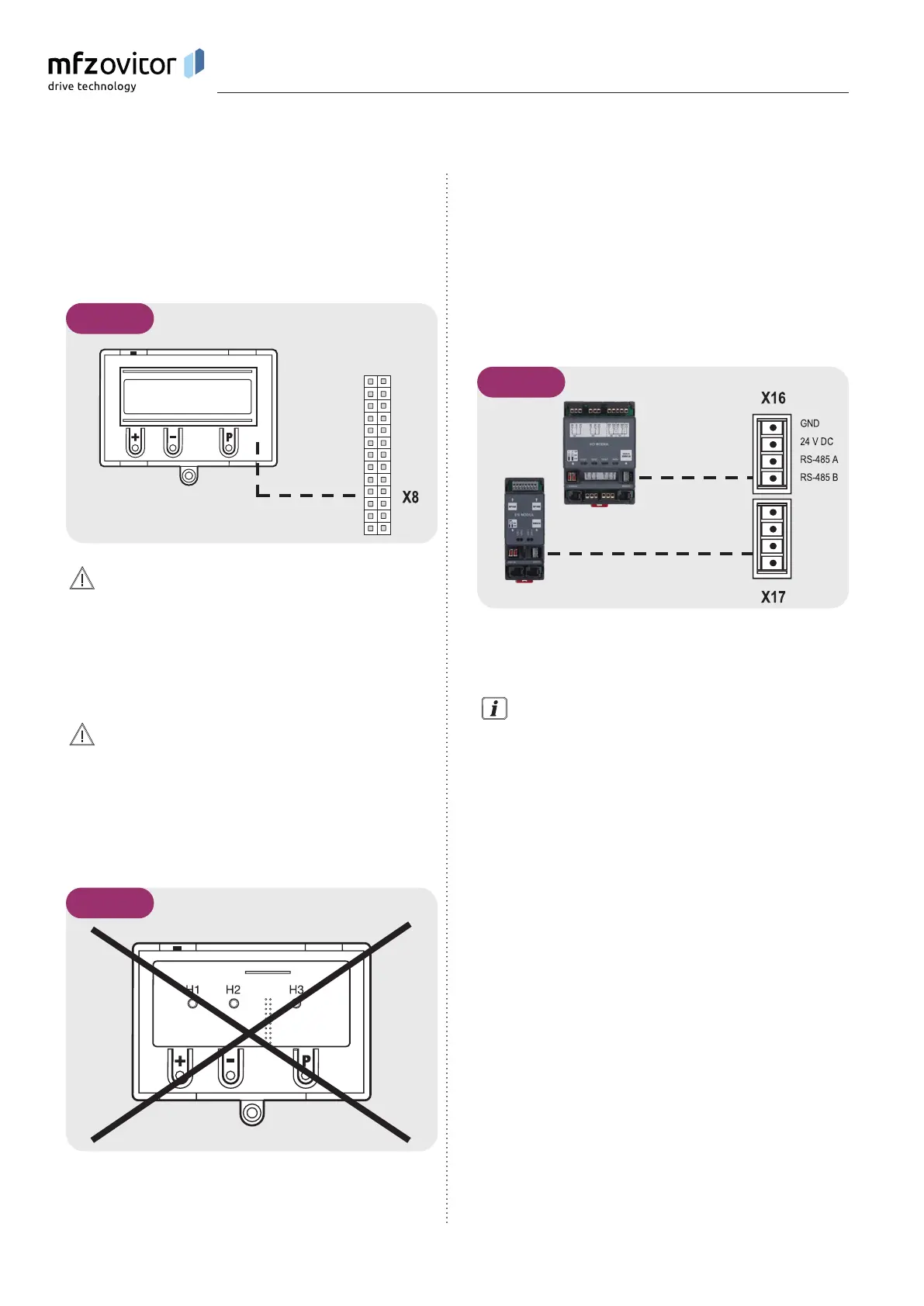
5.13 5.13 Connection of LCD monitorConnection of LCD monitor
With the LCD monitor, you have complete access to all of the
menu settings and parameters of the control unit.
➔ “8. Programming“
5.13 / 1
Damage can occur through improper installation!
The mains power supply must be switched off before
connecting the LCD monitor. Only an MFZ LCD monitor
(article number 91447) may be used.
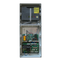
ATTENTION!
Damage can occur through improper installation!
The MFZ LED module (article number 103239) cannot
be combined with the CS 310. Inserting this module and
putting it into service can damage the CS 310 circuit board
beyond repair.
5.13 / 2
5.14 5.14 Connection of MS BUS modulesConnection of MS BUS modules
The MS BUS function modules allow you to expand the
existing functions or add further functions.
− ES Module: Evaluation of draw in protection
systems
− I/O Module: Input/Output expansion
− GVModule: Two-waytrafccontrol
B
A
5.14 / 1
A ES Module
B I/O Module / GV Module
For a detailed description of the function and connection of
the modules, see the separate documentation for the BUS
modules.
NOTICE:
Sockets X16 and X17 can be used only once. Taking the
power consumption into account, however, it is possible to
connect several BUS modules by using special jumper cables.
Installation