8 – Control CS 310 / Rev.I 1.55 Control CS 310 / Rev.I 1.55 – 9
Installation
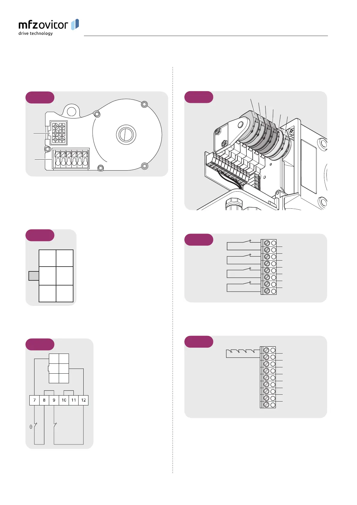
5.5 5.5 Connection of mechanical limit switches Connection of mechanical limit switches
(terminal blocks X15 and X2)(terminal blocks X15 and X2)
5.5 / 1
S1
S2
S3
S4
S5
S6
Terminal block X15
1
2
3
4
5
6
7
8
S2
S5
S1
S6
5.5 / 2
Terminal block X2
S3
S4
S7
S8
U
V
W
B1
B2
5.5 / 3
5.4 5.4 Allocation of connections for absolute Allocation of connections for absolute
value encoder (sockets X11)value encoder (sockets X11)
5.4 / 1
A
B
A: AWG plugs
B: AWG plug terminal
X11 sockets (at connection A)
4 7
grey yellow
5 8
green pink
6 9
white brown
5.4 / 2
Depending on the operator, cables
with either numbered or coloured
wires are used for the AWG:
4 (grey): Safety circuit input
5 (green): RS 485 B
6 (white): GROUND
7 (yellow): RS485 A
8 (pink): Safety circuit output
9 (brown): 12V
DC
Sockets B (absolute value encoder only)
5.4 / 3
C D
C: Thermal element in door/
gate operator
D: Emergency manual
operation (emergency
hand crank or emergency
hand chain)
The end position system will be
recognised automatically by the
control during initial use. If a
change is made at a later date,
the relevant end position system
must be selected via a parameter
setting in INPUT mode.