TERMINAL CONNECTIONS
Connect the unit as in the diagram below or refer to the connection diagram on the side of the unit.
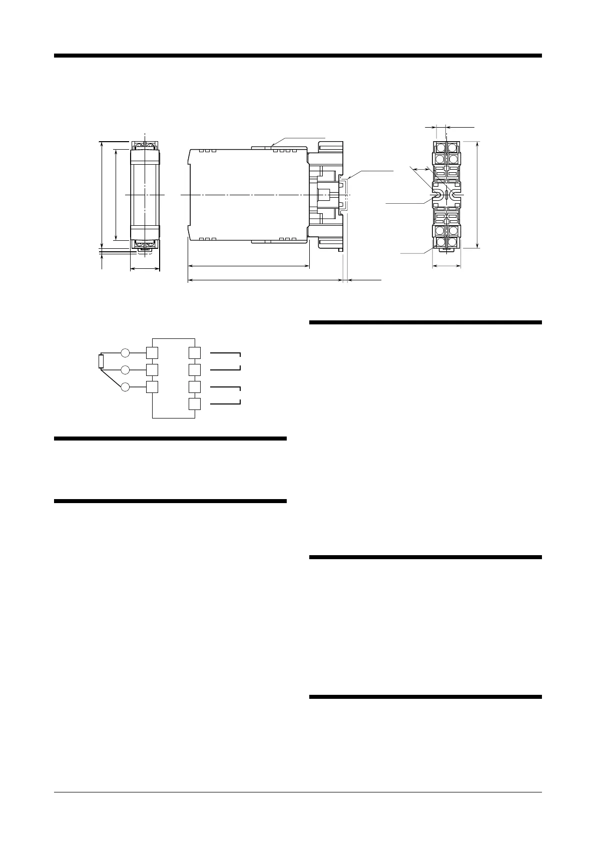
■ EXTERNAL DIMENSIONS unit: mm (inch)
12
34
7
6
8
5
3 (.12)2 (.08)
26 (1.02)
107 (4.21) 26 (1.02)
93 (3.66)
15
(.59)
2–4.5 (.18)
HOLE
15 (.59) deep
DIN RAIL
35mm wide
[3.3 (.13)]
8–M3.5
SCREW
93 (3.66)
CLAMP
(top & bottom)
137 (5.39)
80 (3.15)
•When mounting, no extra space is needed between units.
7.8 (.31)
■ CONNECTION DIAGRAM
+
–
OUTPUT
5
6
+
–
POWER
7
8
1
2
A
B
B
RTD
3
WIRING INSTRUCTIONS
■ SCREW TERMINAL
Torque: 0.8 N·m
CHECKING
1) Terminal wiring: Check that all cables are correctly con-
nected according to the connection diagram.
2) Power input voltage: Check voltage across the terminal
7 – 8 with a multimeter.
3) Input: Check voltage across the terminal 1 – 2 with a
sensitive voltmeter (With 20°C or 68°F, approx. 220mV
with Pt 100, approx. 110mV with Pt 50 Ω).
If RTD wires are broken, the output goes over 100% (be-
low 0% with downscale) due to burnout function. Check
leadwires in such a case.
4) Output: Check that the load resistance meets the de-
scribed specifications.
ADJUSTMENT PROCEDURE
This unit is calibrated at the factory to meet the ordered
specifications, therefore you usually do not need any cali-
bration.
The output signal can be finely adjusted to match it to a re-
ceiving instrument, or to compensate input wire resistance
when the unit is combined with a zenor barrier. Follow the
regular calibration procedure explained below:
■ HOW TO CALIBRATE THE OUTPUT SIGNAL
Use a signal source and measuring instruments of sufficient
accuracy level. Turn the power supply on and warm up for
more than 10 minutes.
1) ZERO: Apply 0% input and adjust output to 0%.
2) SPAN: Apply 100% input and adjust output to 100%.
3) Check ZERO adjustment again with 0% input.
4) When ZERO value is changed, repeat the above proce-
dure 1) – 3).
MAINTENANCE
Regular calibration procedure is explained below:
■ CALIBRATION
Warm up the unit for at least 10 minutes. Apply 0%, 25%,
50%, 75% and 100% input signal. Check that the output
signal for the respective input signal remains within accu-
racy described in the data sheet. When the output is out of
tolerance, recalibrate the unit according to the “ADJUST-
MENT PROCEDURE” explained earlier.
LIGHTNING SURGE PROTECTION
We offer a series of lightning surge protector for protec-
tion against induced lightning surges. Please contact us to
choose appropriate models.
HR / HRS
EM-3413 Rev.5 P. 2 / 2
MG CO., LTD. www.mgco.jp
5-2-55 Minamitsumori, Nishinari-ku, Osaka 557-0063 JAPAN
 Loading...