LC/LCS
EM-1355 Rev.6 P. 4 / 4
MG CO., LTD. www.mgco.jp
5-2-55 Minamitsumori, Nishinari-ku, Osaka 557-0063 JAPAN
SIMPLE LOOP TEST OUTPUT Option /E2
Simulated 0% and 100% output is available with Option /E2.
Switch the Loop Test Selector positions.
Top position: 0% fixed
Middle position: 100% fixed
Bottom position: Cancel the loop test mode
(Back to the normal operating mode)
CHECKING
1) Terminal wiring: Check that all cables are correctly con-
nected according to the connection diagram.
2) Power input voltage: Check voltage across the terminal
7 – 8 with a multimeter.
3) Strain gauge: Check the bridge resistance. Maximum
current is 65mA with excitation 7.5V or less, 35mA with
over 7.5V. Check resistance of load cells.
4) Input: When applying maximum load, check voltage
across the terminal 10 (+) – 11 (–) equals Exc. × Strain
Gauge Sensitivity.
5) Output: Check that the load resistance meets the de-
scribed specifications.
ADJUSTMENT PROCEDURE
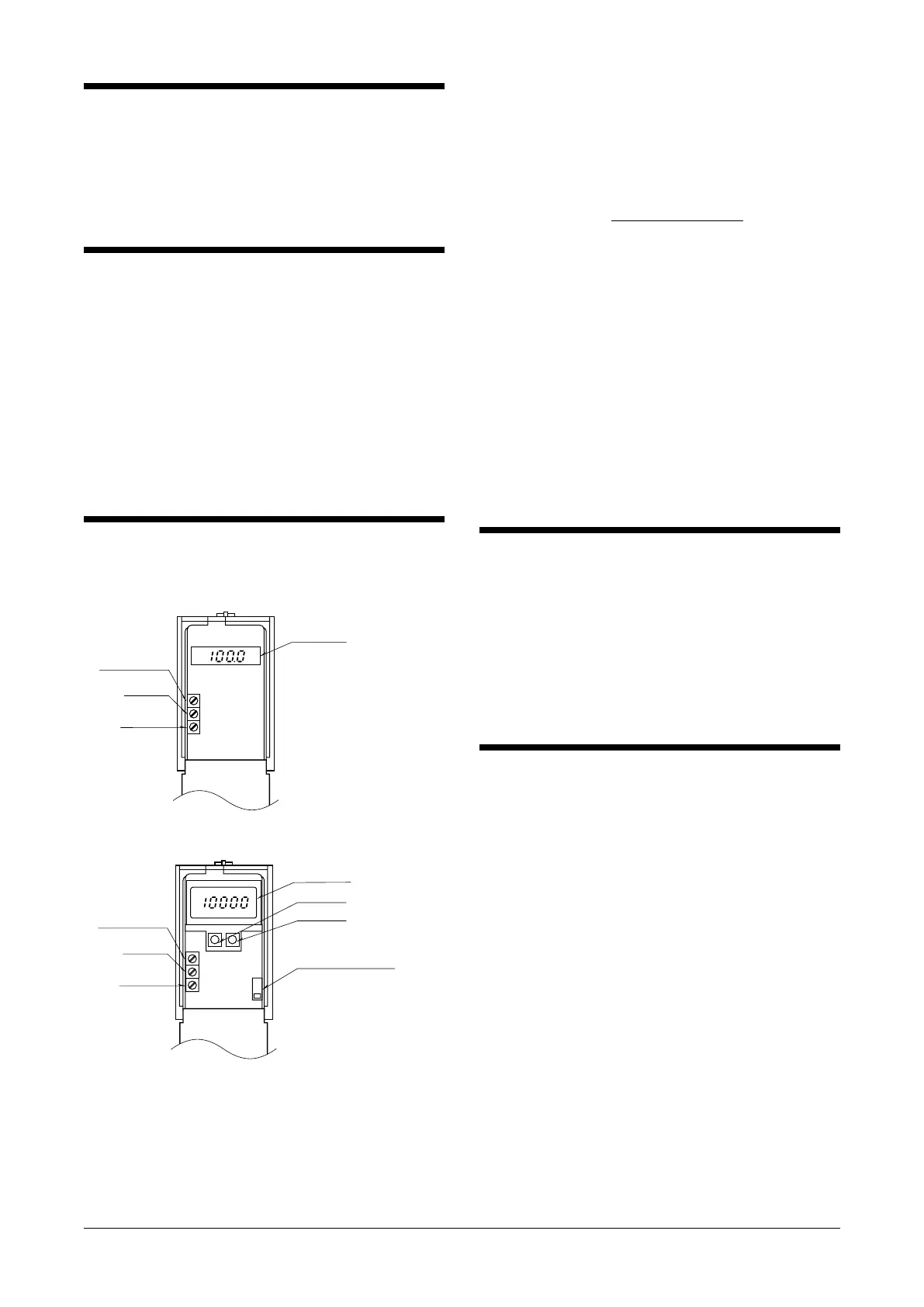
■ FRONT PANEL CONFIGURATION
LCD Meter
Span Adj.
Zero Adj.
Excitation Adj.
Loop Test Selector
Top
Middle
Bottom
: 0% fixed
: 100% fixed
: Cancel
(normal operating mode)
NEXT Key
ENTER Key
LCD Meter
Span Adj.
Zero Adj.
Excitation Adj.
• Option /E
■ EXCITATION ADJUSTMENT
The excitation voltage is calibrated at the factory, therefore
will not usually require adjustment, except when used in
combination with a strain gauge of sensitivity other than
described on the specifications.
In that case, adjust to the value calculated by the following
equation:
Excitation [V] =
5 [V] × a [mV/V]
b [mV/V]
where a:
Factory set sensitivity value marked on the product
b: User’s sensitivity value
Adjustable range is within 2V to 10V with bridge resistance
of 350Ω. When the calculated value exceeds 10V, adjust it
to 10V.
■ ZERO (TARE) ADJUSTMENT
Adjustable from 0 to 80% of the input span (strain gauge
rating). With no load applied, turn the Zero Adjustment
until the output shows 0%.
■ SPAN (SENSITIVITY) ADJUSTMENT
Adjustable from 20 to 100% of the input span (strain gauge
rating). With the full-scale load, turn the Span Adjustment
until the output shows 100%.
MAINTENANCE
Regular calibration procedure is explained below:
■ CALIBRATION
Warm up the unit for at least 10 minutes. Apply 0%, 25%,
50%, 75% and 100% input signal. Check that the output
signal for the respective input signal remains within accu-
racy described in the data sheet. When the output is out of
tolerance, recalibrate the unit according to the “ADJUST-
MENT PROCEDURE” explained earlier.
LIGHTNING SURGE PROTECTION
We offer a series of lightning surge protector for protec-
tion against induced lightning surges. Please contact us to
choose appropriate models.
 Loading...