EM-8175 Rev.7 P. 2 / 4
MAX
MG CO., LTD. www.mgco.jp
5-2-55 Minamitsumori, Nishinari-ku, Osaka 557-0063 JAPAN
INSTALLATION
Detach the yellow clamps located at the top and bottom of the
unit for separating the body from the base socket.
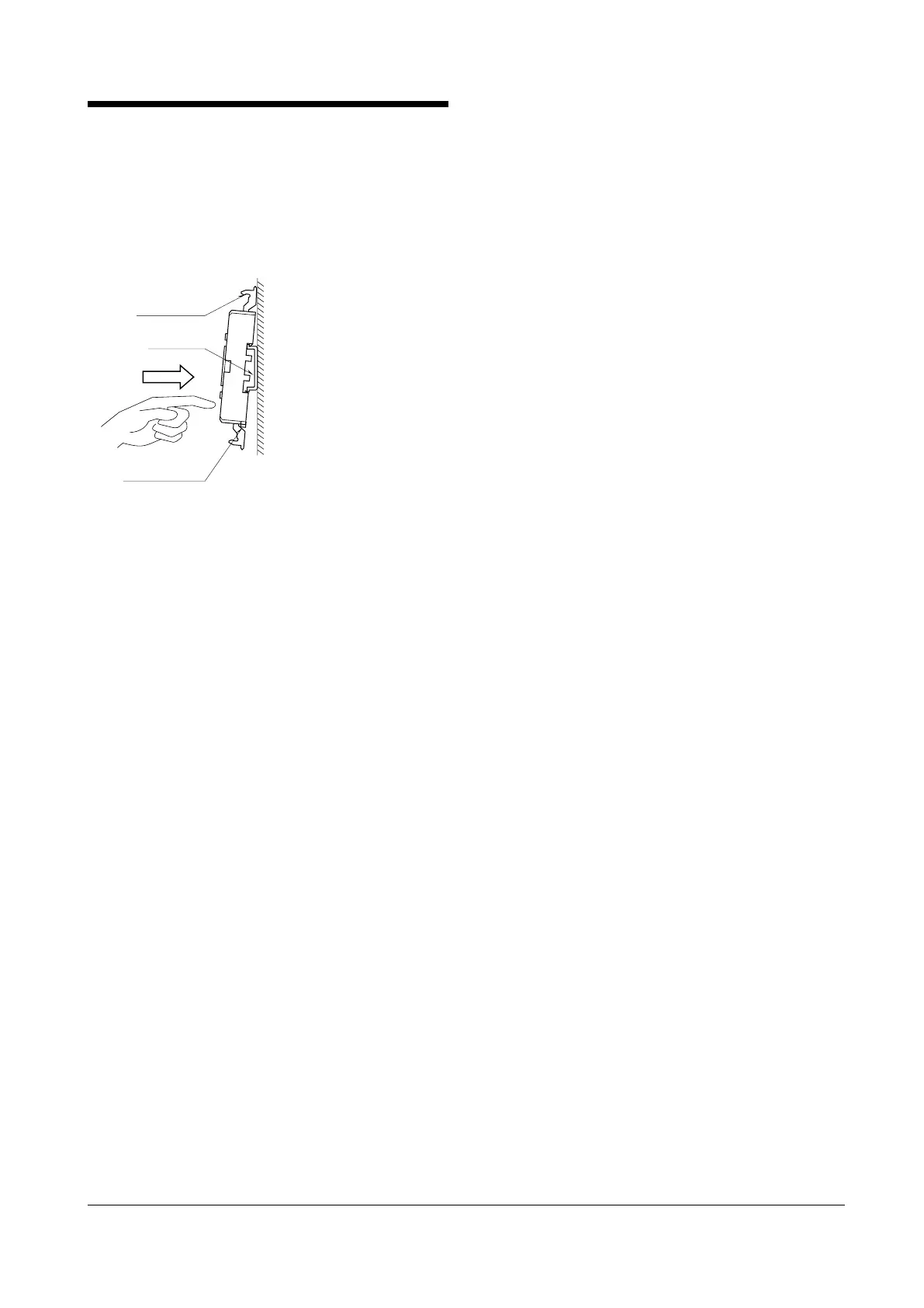
■ DIN RAIL MOUNTING
Set the base socket so that its DIN rail adapter is at the bottom.
Hung the upper hook at the rear side of base socket on the DIN
rail and push in the lower. When removing the socket, push
down the DIN rail adapter utilizing screwdriver (–) and pull.
Clamp
(top & bottom)
DIN Rail
35mm wide
Spring Loaded
DIN Rail Adaptor
Shape and size of the base socket
are slightly different with various
■ WALL MOUNTING
Refer to the next drawings.
■ GROUNDING
A cross-over wire between M-RESTER and ground or metallic