EM-8175 Rev.7 P. 3 / 4
MAX
MG CO., LTD. www.mgco.jp
5-2-55 Minamitsumori, Nishinari-ku, Osaka 557-0063 JAPAN
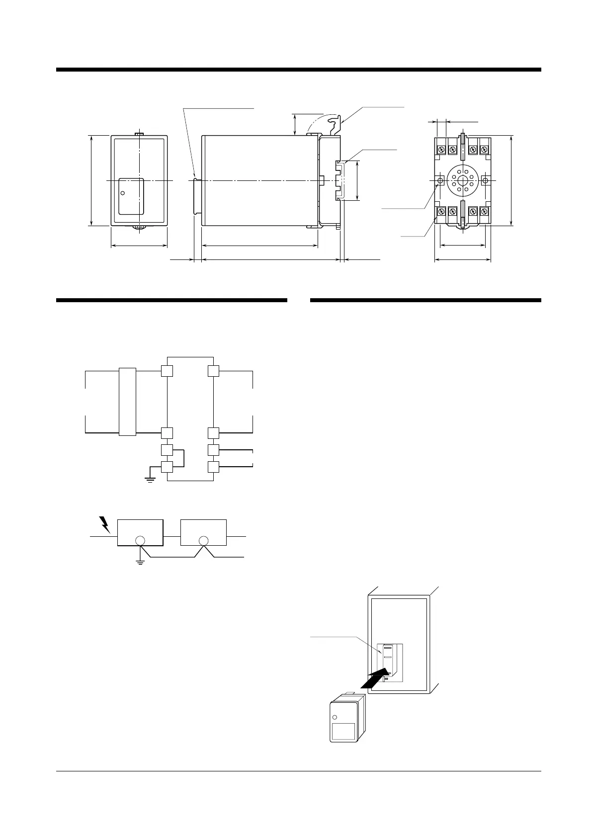
EXTERNAL DIMENSIONS unit: mm (inch)
3456
2187
50 (1.97) 103 (4.06)
123 (4.84)7 (.28) [3.3 (.13)]
80 (3.15)
20
(.79)
35.4 (1.39)
40 (1.57)
50 (1.97)
7.8 (.31)
(top & bottom)
DIN RAIL
35mm wide
ELEMENT (model: MEL)
2–4.5 (.18) dia.
MTG HOLE
15 (.59) deep
8–M3.5
SCREW
•When mounting, no extra space is needed between units.
TERMINAL CONNECTIONS
Connect the unit as in the diagram below.
Be sure to cross-wire between the Ground terminal (2 or 7) and
metallic housing of the protected equipment. (100 Ω max.)
4
5
3
6
ALARM OUTPUT
PROTECTED
EQUIPMENT
(load side)
1
8
2
7
POWER
SOURCE
(surge side)
BREAKER
Be sure to install
the Breaker.
B
■ GROUNDING
M-RESTER
PROTECTED
EQUIPMENT
G
G
CROSSOVER WIRE
GROUNDING
(100
Ω or less)
A crossover wire between M-RESTER ground and the ground or
metallic housing of the equipment is required for protection.
SURGE ABSORBER ELEMENT
When a strong lightning surge exceeding discharge current
capacity of lightning arrester enters to power supply cables,
conventional lightning arrester cuts off the supply line with its
fuse blown in order to prevent ignition.
The model MAX is designed to separate its surge absorber element
(model: MEL) from power supply lines when there is anomaly
with the element. It ensures no interruption of power supply
and thus the plant itself.
The MEL indicates its failure with contact output (ON) and front
indicator (turns white). In such condition, maximum surge volt-
age may be up to 800 V. Replacing the MEL as soon as possible
is recommended.
■ REPLACING THE MEL
Replacing the MEL is very simple without interruption of power
supply.
Pull the MEL off from the main body, and replace with a new one.
Insert it to the connector. (See the figure below.)
The replacement MEL is available with following model No.
MEL-100: for 100V/110V/120V AC power
MEL-200: for 200V/220V/240V AC power
We recommend that you keep spare MELs so that you can replace
them when necessary.
MEL
 Loading...