EM-8175 Rev.7 P. 4 / 4
MAX
MG CO., LTD. www.mgco.jp
5-2-55 Minamitsumori, Nishinari-ku, Osaka 557-0063 JAPAN
MAINTENANCE
Check M-RESTER periodically. Many cases of lightning are
ignored, and even lightning at a far distance often causes in-
ductive surges.
We recommend that you check your M-RESTER about twice a
year, before and after the rainy season. Check whenever you
experience a strong lightning occurrence.
Checking procedure is explained in the following:
■ CHECKING
WIRING
• Make sure that wiring is done as instructed in the connection
diagram.
• Make sure that the Ground terminal (2 or 7) is connected to
the metallic housing of protected equipment.
• Make sure that the Ground terminal (2 or 7) is grounded to earth.
ALARM CONTACT AND INDICATOR
• M-RESTER is designed to protect the equipment even when
subjected to a lightning surge exceeding its discharge cur-
rent capacity to certain extent. However, in such a case, the
insulation of its discharge element may fail. When it hap-
pens, a relay contact turns ON and the indicator on the front
panel of M-RESTER turns white.
Replace the surge absorber element, model MEL according
to the procedure described in the left.
DISCHARGE FUNCTION
Remove the MEL and test its discharge capability as follows:
• Check resistance across the terminals (B) – (L) (infinite
standard).
• Check that discharging occurs across the same terminals with a
1000 V DC megger. (Indicator of the megger reaches over-scale.)
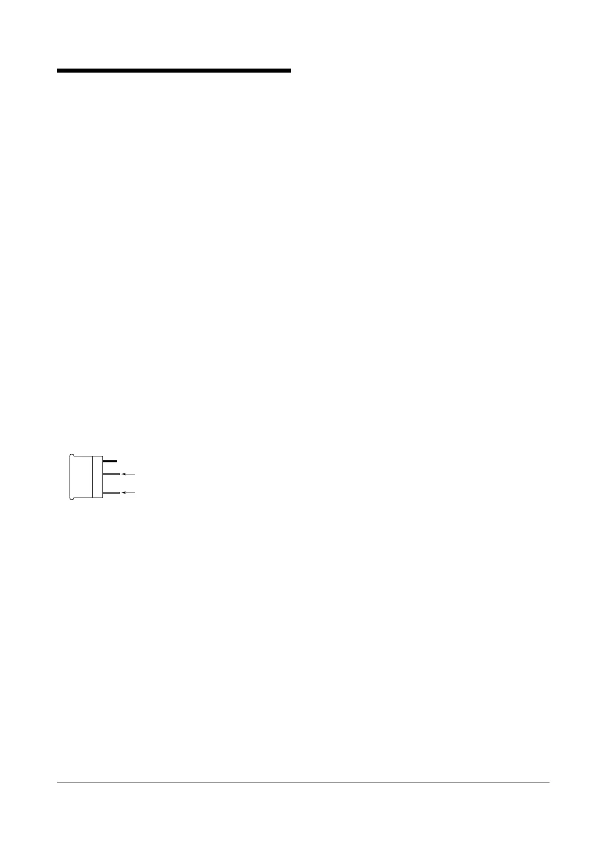
L
B
MEL SIDE VIEW
LEAKAGE CURRENT (between lines)
Return the MEL and apply supply voltage across the terminals
(1) – (8) with no load, and measure current at the terminal (1).
(≤ 1 mA standard)
• If any of the above tests shows negative, replace the MEL after
that you confirm that the main body unit functions properly
with the following tests. If the following tests show negative,
replace the whole M-RESTER unit.
MAIN BODY UNIT TEST
• Remove the MEL and all wiring and check resistance across
the following terminals. (≤ 0.5 Ω standard)
Terminals (1) – (4), (5) – (8)
• With the MEL and all wiring detached, check resistance across
the following terminals. (infinite standard)
Terminals (1) – (8), (1) – (7), (7) – (8)
• Check that discharging occurs across the same terminals with a
1000 V DC megger. (Indicator of the megger reaches over-scale.)
 Loading...