MG CO., LTD. www.mgco.jp
5-2-55 Minamitsumori, Nishinari-ku, Osaka 557-0063 JAPAN
TERMINAL CONNECTIONS
Connect the unit as in the diagram below or refer to the connection diagram on the side of the unit.
Do not interconnect negative sides of input and output terminals (via grounding terminals e.g.) as they are not of the same
potential level.
Ground the terminal 6 for RFI protection if necessary. When grounded, dielectric strength between output signal line and
ground is of 50V DC, though it is of 500V AC when not grounded.
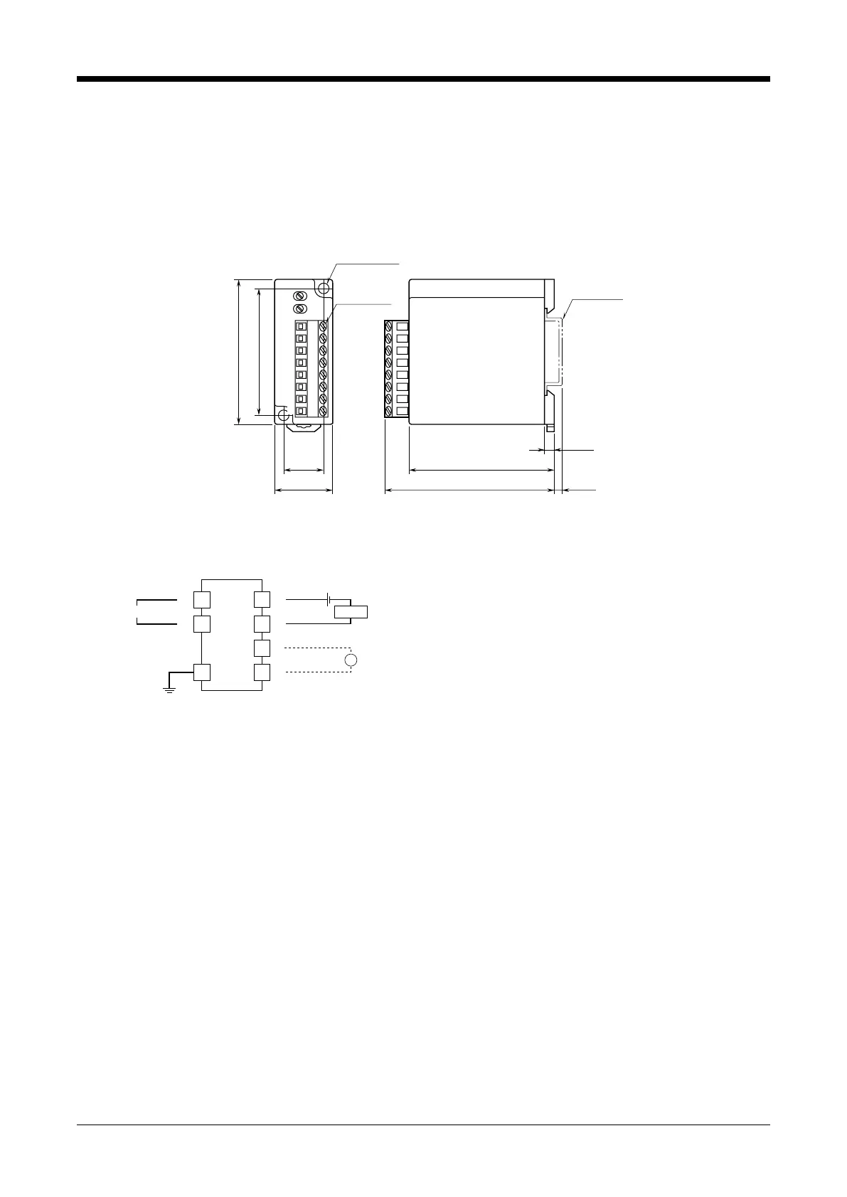
■ EXTERNAL DIMENSIONS unit: mm (inch)
EURO TYPE
TERMINALS
DIN RAIL
35mm wide
18 (.70)
25 (.98)
53 (2.08)
60 (2.36)
60 (2.36)
4 (.15)
3.3 (.12)70 (2.76)
2–4.4 (.17) dia.
MTG HOLE
1
2
3
4
5
6
7
8
•When mounting, no extra space is needed between units.
■ CONNECTION DIAGRAM
3
4
6
7
8
–
mA
MONITOR
+
–
+
–
LOAD
2
1
OUTPUT
24V DC
4 – 20mA DC
+
+
–
INPUT
TVS
EM-3318 Rev.6 P. 2 / 3