Do you have a question about the micro-trak Calc-An-Acre II and is the answer not in the manual?
Details on how to mount the main console unit securely and in an optimal location.
Instructions for connecting the Calc-An-Acre II to a 12VDC power source and ensuring proper setup.
Guidelines for safely routing the system's cables to prevent damage and ensure longevity.
Correct positioning of wiring branches to protect internal connections from liquid chemicals.
Steps to connect the power cable to a switched +12VDC source or directly to the battery.
Overview of available speed sensors compatible with the Calc-An-Acre II system.
Specific instructions for installing the Astro series GPS speed sensor receiver and module.
Detailed guide for installing magnetic wheel or drive shaft speed sensors.
Procedure for connecting the speed sensor cable to the main harness and console.
Instructions for installing the optional remote Run/Hold sensor kit for operational control.
Guide for installing the optional shaft RPM sensor kit for accurate RPM readings.
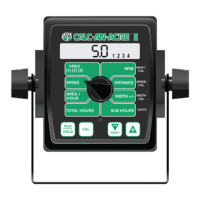
Explanation of the Calc-An-Acre II's display elements and functions.
Explanation of the rotary dial positions used for system calibration.
Details on the purpose and operation of the console's main buttons.
Procedure for selecting between English, Metric, or Turf measurement units.
Steps for inputting specific calibration numbers for sensors and system settings.
Table and guidance for entering speed calibration values for various radar and GPS sensors.
Method for calculating the speed calibration value based on wheel circumference.
Guidance for calibrating speed sensors mounted on drive shafts.
Procedure for precisely adjusting speed and distance calibration for accuracy.
Basic operation principles and how to power the console on and off.
How to interpret the display and use the rotary switch to select functions.
Explanation of how to use the Run/Hold button to start and stop counters.
How to adjust working width during operation for varying field conditions.
Detailed description of each function accessible via the rotary switch.
Procedure for resetting area, distance, total hours, and sub hours counters.
Explanation of error messages and warning indicators displayed by the console.
General advice and initial checks for resolving system problems.
Troubleshooting steps for dead console or erratic/zero speed readings.
Resolving inaccuracies in distance/area counts and erratic console behavior.
Correcting measurement mode settings and handling counter overflow (OFL).
Steps to test the functionality of console, harness, and sensors.
Procedures for testing Hall-effect sensors using a multimeter.
Specific troubleshooting steps for Vansco radar speed sensors.
Using a multimeter to test console inputs for proper signal reception.
Testing specific input signals for speed, RPM, and Run/Hold functions.
Guides for installing speed sensors on various wheel types and drive shafts.
Specific mounting instructions for implement wheels, tractor wheels, and ATV wheels.
Detailed instructions for mounting speed sensors on vehicle drive shafts.
List and pinout details for various radar Y adapter cables.
Reference table for converting between English and Metric units.
Catalog of available replacement parts with part numbers and descriptions.
The Micro-Trak Calc-An-Acre II is an electronic monitor designed to provide real-time data on speed, area worked, distance traveled, and shaft RPM. It is engineered for ease of installation and operation, suitable for various agricultural and turf applications. The console features a large, easy-to-read liquid crystal display with a lighted display for visibility in different conditions.
The Calc-An-Acre II offers several key monitoring functions:
The system operates on a 12VDC negative ground electrical system. It is equipped with non-volatile memory, ensuring that daily totals and calibration values are retained even without a constant power supply.
Speed Sensor Options: The Calc-An-Acre II can interface with various speed sensors:
Calibration Values (Default):
Console Controls:
Calibration: The Calc-An-Acre II supports English, Metric, and Turf measurement units. The unit can be switched between English and Metric modes by holding down the "CAL" and "-" keys while powering on, then entering and exiting calibration to lock in the selection. Turf units are similar to English, but Area is displayed in thousands of square feet.
Fine Tuning Speed/Distance Calibration: A precise procedure is outlined for fine-tuning the speed/distance calibration value. This involves driving a measured course (e.g., 1000 feet or 500 meters) and adjusting the calibration value to match the actual distance traveled.
Width Reduction - On-The-Go (OTG): The effective working width can be reduced in 25% increments during operation. This feature is accessed by turning the rotary switch to "WIDTH +/-" and using the "+" or "-" keys. The display shows the current effective width and the reduction status (e.g., "1 2" for 50% width). When the system is put into HOLD, the width automatically reverts to the calibrated full width.
Resetting System Counters: AREA, DISTANCE, TOTAL HOURS, and SUB HOURS counters can be reset independently. To reset, put the system in HOLD, turn the rotary switch to the desired counter, and hold the "RESET" button until the display reads zero. For AREA counters, the "+" button is used to select the specific counter (1, 2, or 3) before resetting.
Care and Maintenance: The console should be stored in a cool, dry location when not in use for extended periods. Care should be taken during cleaning to prevent water or other liquids from entering the case.
Troubleshooting: The manual provides comprehensive troubleshooting guidance for various issues, including:
Replacement Parts: A list of replacement parts is provided, including part numbers and descriptions for console components, speed sensor kits, magnets, cable ties, and various extension cables (3-Pin and 10-Pin Metri-Pack 150).
| Brand | micro-trak |
|---|---|
| Model | Calc-An-Acre II |
| Category | Control Systems |
| Language | English |