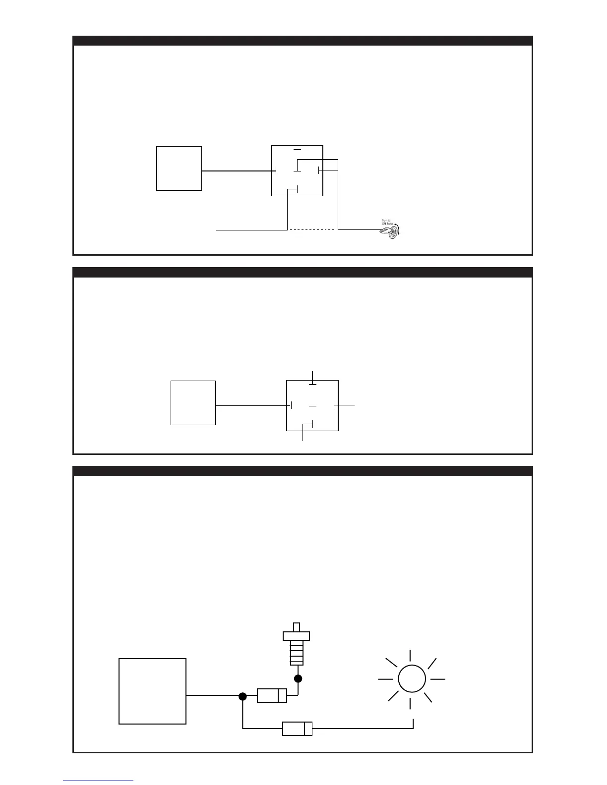
ORANGE: ARMED OUTPUT (FOR STARTER-KILL RELAY)
This Output Will Provide A (-) Negative Signal ONLY When The Alarm Is Armed. This Output Can Be Used To Supply
Ground To One Side Of a Starter-Kill Relay’s Coil. The Other Side Of This Relay’s Coil Will Require A (+) 12 Volt Signal
Supplied By The Ignition Switch (ONLY When The Ignition Is Turned On Or When The Starter Motor Is Cranking). In This
Manner There Will ONLY Be A Current Draw If There Is A Start Attempt While The Alarm Is Armed.
It Will Be Necessary To Locate And Cut The Vehicle’s Starter Motor Wire:
• This Wire Will Show (+) 12 Volts ONLY When The Vehicle’s Starter Motor Is Actually “CRANKING”, If The
Starter Motor Is Not Cranking This Wire Will Usually Rest At Ground. (SEE DIAGRAM)
BLUE: HOOD/TRUNK (-)INSTANT TRIGGER INPUT
The Hood/Trunk (-) Input Is An Instant Trigger Zone.
• This (-) Input will Trigger The Alarm If it Becomes Grounded While The Alarm Is Armed.
• If This (-) Input Is Grounded At The Time The Alarm Is Armed, The Unit Will By-Pass This Particular Zone Until It
Becomes Ungrounded.
• If This (-) Input Is Grounded Before The Alarm Is Armed, The Unit Will NOT Passively Arm (Self-Arm) Until The Input
Is Ungrounded. (The Hood/Trunk Is Closed)
CONNECT The Alarm’s Blue Wire To An Aftermarket or Factory (-) Pin-Switch/Mercury Switch or A (-) Trunk Light
Circuit Which Shows Ground ONLY When The Vehicle’s Hood Or Trunk Is Open.
NOTE: It Is Necessary To DIODE ISOLATE All Circuits And/Or Devices If Connecting The Alarm’s Blue (-) Input Wire
To More Than One Circuit Or Device. (SEE DIAGRAM)
P3
8008_inst.7/7/04.qx
BLACK/WHITE: (-) DOME-LIGHT ILLUMINATION OUTPUT: (Relay Required)
The Alarm’s Black/White Wire Will Provide A 30-Second (-) Negative Output For Illuminating The Vehicle’s Dome-Light
When The Alarm Is Disarmed. (A Relay Is Required) (SEE DIAGRAM)
• This Output Will Reset If The Alarm Is Armed/Disarmed Or If The Vehicle’s Ignition Is Turned On.
WARNING: Do Not Connect The Alarm’s Black/White Wire Directly To The Dome-Light Circuit Or Severe Damage Will
Occur To The Unit.
 Loading...