EasyManua.ls Logo

Microelettrica Scientifica MC2-30M - User Manual

Microelettrica Scientifica MC2-30M
64 pages
Print Icon
To Next Page IconTo Next Page
Loading...
MC2-30M
Doc. N° MO-0495-ING
Copyright 2018
17.03.2022
Rev.
2
Pag.
1
of
64
MICROPROCESSOR
MOTOR PROTECTION
RELAY
TYPE
MC2-30M
OPERATION MANUAL

Table of Contents

Question and Answer IconNeed help?

Do you have a question about the Microelettrica Scientifica MC2-30M and is the answer not in the manual?

Summary

Microprocessor Motor Protection Relay MC2-30 M Operation Manual

1. General Utilization and Commissioning Directions

General Usage and Safety Precautions

Covers storage, installation, electrical connections, safety, handling, and disposal.

Maintenance and Fault Management

Details maintenance procedures and fault detection/repair.

2. General Relay Features

2.1 Power Supply Options

Details the available power supply types for the relay.

3. Front Panel Overview

4. Keyboard and Display Interface

4.1 Display Information

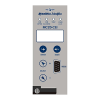
Explains the LCD display capabilities and information shown.

Keyboard Navigation Controls

Describes the function of the front panel push-buttons for navigation.

5. Display Icons Guide

6. Signalization and Status Indicators

Signal LED Overview and Reset

Details the 11 signal LEDs, their meaning, and manual reset procedure.

Last Trip Display Information

How to view the last recorded trip event on the display.

7. LED Configuration via Software

7.1-7.6 LED Configuration Parameters

7.7 Function Assignment Table for LEDs

7.8 Example: Configuring Led1 Settings

7.8.1 Link Enable Configuration

How to set the link enable status for an LED.

7.8.2 Light Programming (Flashing)

How to set an LED to flash.

7.8.3 Function Mode (Latched)

How to set the function mode to latched for an LED.

7.8.4 Function Selection (1 I>)

How to assign a specific function (e.g., 1I>) to an LED.

8. User Variables Configuration

8.1-8.8 User Variable Parameters

Details parameters for user variables: Name, Description, Linked Functions, OpLogic, Timer, Timer Type, Extra, Logical Status.

8.9 Example: Setting a User Variable

Practical example of configuring a user variable.

8.9.1 Setting User Description

8.9.2 Linking Functions to User Variables

8.9.3 Configuring Operation Logic

8.9.4 Setting Timer Delays

8.9.5 Selecting Timer Type

8.9.6 Setting Extra Time

9. Local Commands Operation

Available Local Commands List

Lists commands like Leds Clear, Relays Clear, C/B control, etc.

Executing a Local Command Example

Step-by-step guide on executing a local command.

10. Real-time Measurements

Accessing Measurement Data

Procedure to navigate the menu and display measurements.

Measured Value Descriptions

Explains each measured parameter (Imx, Ia, Ib, Ic, Io, I1, I2, Tem, tst).

11. Maximum Demand Values

Accessing Maximum Values

Procedure to navigate the menu and display maximum values.

Maximum Value Parameter Descriptions

Explains each maximum value parameter (Imx, Ia, Ib, Ic, Io, I1, I2, Tem).

12. Trip Recording and Analysis

Displaying and Viewing Trip Records

Procedure to access and view trip event logs and details.

Erasing Trip Records

Procedure to clear all recorded trip events.

13. Partial Operation Counters

Displaying and Resetting Partial Counters

Procedure to access, view, and reset the count of operations per function.

14. Total Operation Counters

Displaying Total Counters

Procedure to access and view the total count of operations per function.

15. Event Logging and Management

Displaying and Viewing Event Details

Procedure to access and view event logs and specific event information.

Erasing Recorded Events

Procedure to clear all recorded events.

15.1 Event Display Reference

16. System Parameters Configuration

16.1 Setting Group Management

How to select and modify system settings within different groups.

CTs & PTs and Ratings Configuration

How to configure Current Transformer, Potential Transformer ratios, and system ratings.

17. Settings Menu Overview

17.1 Variable Settings and Groups

Lists variables available in both setting groups, covering communication, customization, file system, and protection functions.

17.1 Modifying Variable Settings

Navigating and Modifying Settings

How to navigate through menus, groups, and parameters to modify settings.

17.2 Password Management

Password Entry Procedure

Step-by-step guide for entering the password using the keypad.

17.3 Communication Settings

17.3.1 Communication Variables

Explains BRRem, PRRem, and Addr. variables for communication.

17.3.2 USB and RS485 Ports

Details USB and RS485 ports for PC and SCADA communication.

17.4 HMI Customization

17.4.1 HMI Variable Descriptions

Explains Lang, Light, and tBckL variables.

Example: Setting Local Language

Step-by-step guide for setting the local language.

17.5 File System and Disk Management

17.5.1 File System Variables

Explains log, OniDF, StopWrite, and DelOldFiles variables.

17.5.2 Downloading Files

How to download journal, fault log, and oscillographic files.

17.6 Thermal Image Function (T>)

17.6.1 Thermal Image Variables

Details variables like Abil., OPMOD, Tal, Is, Tres, To.

17.6.2 Trip and Alarm Logic

Explains the heat accumulation algorithm and trip conditions.

17.6.2.1 Thermal Image Trip Time Calculation

Formula and explanation for calculating trip time based on current.

17.6.2.2 Thermal Image Curves

17.7 First Overcurrent Element (1 I>)

17.7.1 Overcurrent Element Variables

Details variables like Enab., f(t), tBI, Is, ts, tBO.

17.7.2 Blocking Logic (BO-BI)

How to use blocking logic for inhibiting operation via external signals.

17.7.3 Inrush Current Threshold Doubling

Feature to double thresholds during current inrush.

17.8 Second Overcurrent Element (2 I>)

17.8.1 Overcurrent Element Variables

Details variables for the second overcurrent element.

17.9 Third Overcurrent Element (3 I>)

17.9.1 Overcurrent Element Variables

Details variables for the third overcurrent element.

17.10 First Earth Fault Element (1 Io>)

17.10.1 Earth Fault Element Variables

Details variables for the first earth fault element.

17.11 Second Earth Fault Element (2 Io>)

17.11.1 Earth Fault Element Variables

Details variables for the second earth fault element.

17.12 Third Earth Fault Element (3 Io>)

17.12.1 Earth Fault Element Variables

Details variables for the third earth fault element.

17.13 First Negative Sequence Element (1 Is>)

17.13.1 Negative Sequence Element Variables

Details variables for the first negative sequence element.

17.13.2 Current Unbalance Element f(t)

Explains the f(t) variable for negative sequence element curves.

17.14 Second Negative Sequence Element (2 Is>)

17.14.1 Negative Sequence Element Variables

Details variables for the second negative sequence element.

17.15 Motor Start Function (MotSt)

17.15.1 Motor Start Variables

Details variables for the motor start function.

17.16 Locked Rotor Function (LR)

17.16.1 Locked Rotor Variables

Details variables for the locked rotor function.

17.17 Start Number Limitation (StNo)

17.17.1 Start Number Limitation Variables

Details variables for the start number limitation function.

17.18 Starting Sequence Control (StSeq)

17.18.1 Starting Sequence Variables

Details variables for the starting sequence control.

17.18.2 Starting Sequence Operation

Explains how the starting sequence control manages motor start-up.

17.19 No Load Running Protection (I<)

17.19.1 No Load Running Variables

Details variables for the no-load running function.

17.19.2 No Load Running Operation

Explains the function's operation for no-load running protection.

17.20 Trip Circuit Supervision (TCS)

17.20.1 TCS Variables

Details variables for the TCS function.

17.20.2 TCS Operation and Wiring

Explains how the TCS function works and its wiring.

17.21 Internal Relay Fault Detection (IRF)

17.21.1 IRF Variables

Details variables for the IRF function.

17.21.2 IRF Operation

Explains the IRF function's operation.

17.22 Breaker Failure Detection (BrkFail)

17.22.1 BrkFail Variables

Details variables for the BrkFail function.

17.22.2 BrkFail Operation

Explains how the breaker failure detection works.

17.23 Oscillographic Recording Function (Oscillo)

17.23.1 Oscillo Variables

Details variables like Enab., Trig, tPre, tPost.

17.23.2 Oscillo Operation

Explains how to trigger and manage oscillographic recordings.

17.23.3 Software-Available Functions

17.23.4 User Trigger Oscillo Configuration

17.23.4.1-17.23.4.8 User Trigger Oscillo Parameters

Details parameters for user trigger logic including Name, OpLogic, Timer, etc.

17.24 Example: Setting Oscillo Trigger Logic

17.25.5.1 Linked Functions Setup

How to link functions to the user trigger for oscillographic recording.

17.20.5.2 Operation Logic for User Trigger

17.20.5.3 Timer Settings for User Trigger

17.20.5.4 Timer Type for User Trigger

17.20.5.5 Extra Time for User Trigger

17.24 CB Management (Control C;B)

17.24.1 CB Management Variables

Explains variables for CB management like L/R, Key, Key0, KeyC, tL/R, tC/Bs.

17.24.2 Push-Button Configuration for CB Control

How to program front panel buttons for CB control actions.

17.24.2.1 Digital Input Configuration for CB

How to configure digital inputs for CB status and commands.

17.24.2.2 User Variables for CB Management

17.24.2.3 Digital Output Configuration for CB

17.24.2.4 Function Settings for CB Management

17.25 External Reset Configuration (ExtResCfg)

17.25.1 External Reset Variables

Explains the ActOn variable for external reset.

18 Input;Output Configuration

18.1 Digital Input Overview

List of programmable digital inputs and their general behavior.

18.2 Digital Input Configuration

How to configure digital inputs to control various functions.

18.2.1 Example: Setting Digital Input Function

18.2.1.5 Assigning Functions to Digital Inputs

How to assign functions to a digital input.

18.3 Physical Output Relays

18.4 Digital Output Configuration

18.4.1 Example Output Configuration

Example of configuring output relays with linked functions and timing.

18.4.2 Output Relay Operation Modes

18.4.2.1 Example: Configuring Output Relay 0.R1

18.4.2.2 Linking Functions to Output Relay

How to link functions to an output relay.

18.4.2.3 Setting Output Configuration

How to set the output configuration (e.g., Normally Denergized).

18.4.2.4 Function and Mode Setting for Output Relay

18.4.2.5 Setting Output Activation Time (tON)

19 Relay Status Monitoring (InfoStatus)

20. Date and Time Configuration

Setting Date, Time, and Day of Week

Step-by-step guide to setting the date, time, and day of the week.

20.1 Clock Synchronization Methods

21 Internal Health Diagnostics

22 Device Information and Version

23 Maintenance and Service Information

24 Wiring Diagram

25 Physical Dimensions and Panel Cutout

26 Electrical Characteristics and Standards

Microelettrica Scientifica MC2-30M Specifications

General IconGeneral
BrandMicroelettrica Scientifica
ModelMC2-30M
CategoryProtection Device
LanguageEnglish

Related product manuals