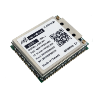
The n920 is a high-performance embedded wireless data transceiver designed for reliable wireless data transfer in the 902-928 MHz ISM band. This frequency-hopping spread-spectrum module is suitable for integration into various equipment that utilizes an asynchronous serial interface. Its compact size and superior RF performance make it ideal for a wide range of applications.
Function Description:
The n920 operates as a wireless data transceiver, enabling communication between terminal devices. It supports both point-to-point and point-to-multipoint network topologies, including repeater operation, allowing for flexible network configurations. Multiple independent networks can operate concurrently in the same or nearby areas without compromising privacy or reliability. The module uses a subset of standard AT style commands, similar to traditional telephone line modems, for ease of installation and use. All units are physically identical and can be configured as a master, repeater, or slave using the AT command set without hardware modifications.
Important Technical Specifications:
- Operating Frequency: 902-928 MHz ISM band (license-free in North America; may require factory configuration for other countries).
- Data Interface: Serial I/O data port with handshaking and hardware flow control.
- Hopping Patterns: 128 sets of user-selectable pseudo-random hopping patterns, designed for multiple network operation, security, reliability, and interference tolerance.
- Encryption: 65536 user-selectable encryption key values for enhanced security and privacy.
- Error Detection: 32-bit CRC error detection with automatic re-transmit for data accuracy and reliability.
- TDMA Support: Time Division Multiple Access support, enabling multi-slave access in point-to-point mode.
- Roaming Ability: Repeaters and slaves can re-synchronize with a new master if the original master's synchronization pulse is lost.
- Receiver Sensitivity: -108 dBm.
- Output Power Level: User-selectable, with a maximum of 30 dBm (1000 mW).
- Maximum EIRP (Effective Isotropically Radiated Power): FCC and IC Regulations allow up to 36 dBm. The sum of transmitted power (in dBm), cabling loss, and antenna gain must not exceed 36 dBm.
- Antenna Connectors: MCX and Reverse Polarity SMA connectors.
- Approved Antennas: A list of approved antennas is provided, including Quarter Wave, Rubber Ducky, Transit, Yagi, Patch, and Omni-Directional types, with varying gains (e.g., <1.5 dBi to 14.15 dBi). Use of unlisted antennas or antennas with gain exceeding 14.2 dBi is prohibited by Industry Canada regulations.
Usage Features:
- Flexible Deployment: Can be used for short- to mid-range wireless communication links between DTEs in almost any situation requiring asynchronous serial data intercommunication.
- Network Configuration: Units can be configured as master, repeater, or slave using AT commands, allowing for diverse network topologies.
- Signal Strength Monitoring: The average signal strength (RSSI) can be verified by entering Command Mode and reading Register S123. A minimum strength of -108 dBm is required for communication, with -95 dBm recommended for consistent reliability.
- Output Power Adjustment: The output power level is user-selectable. It is recommended to use the lowest power necessary to avoid unnecessary "RF pollution" and to establish a reliable link based on RSSI.
- Gain Margin Calculation: System gain, path loss, and interference are critical factors for successful communication. A gain margin of at least 20 dB is recommended for reliable communication.
- Antenna Selection: The choice of antenna (e.g., Yagi for fixed point-to-point, Omni-directional for multiple units or mobile applications) should consider path loss and equipment topology.
- Cable Selection: Recommended coax cables include LMR 195, LMR 400, and LMR 600, with varying loss characteristics (dB/100ft). Factors like price, bend radius, performance requirements, and distance to the antenna should be considered.
Maintenance Features:
- Installation Guidelines: Detailed procedures for installing internal cabling, external cables, antennas, and lightning arrestors are provided.
- RF Exposure Safety: A separation distance of 23 cm or more must be maintained between the antenna and persons during device operation to satisfy FCC RF exposure requirements. The antenna must not be co-located with any other antenna or transmitter.
- Equipment Labeling: The manufacturer, product name, and FCC/IC identifiers must appear on the outside label of the end-user equipment.
- Surge Arrestors: Installation of two lightning (surge) arrestors (one at the antenna, one at the equipment interface) is recommended for protection against lightning. The grounding system should be fully integrated with tower and power grounding.
- External Filter: An external cavity filter from Microhard Systems can be used to eliminate RF noise in environments with close proximity to paging towers or cellular base stations that might desensitize the receiver.
- Weatherproofing: Type N and RTNC connectors are not weatherproof and should be taped with rubber splicing tape and coated with a sealant.
- Cable Installation: Cables should be fastened at the top near the antenna connector/surge arrestor and at 5 ft intervals down the tower, ensuring not to over-tighten fasteners. Proper grounding of cables to the tower is essential.
- Warranty: Microhard Systems Inc. provides a one-year warranty against defects in material and workmanship. The warranty covers repair or replacement of non-conforming products but excludes defects caused by negligence, misuse, mistreatment, or alterations.
- Regulatory Compliance: The device complies with Part 15 of the FCC Rules and Industry Canada regulations, ensuring operation is subject to conditions that prevent harmful interference and require acceptance of any received interference.
- User Responsibility: Users are warned that changes or modifications not expressly approved by Microhard Systems Inc. could void their authority to operate the equipment. Fixed antennas require installation preventing end-users from replacing them with non-approved antennas.