Do you have a question about the Micronics U1000MKII-FM and is the answer not in the manual?
Describes the installation and use of the U1000MkII flow and heat meters.
Explains the cross correlation transit time algorithm and temperature sensing for flow and heat measurement.
Lists the components included in the U1000MkII unit and kit, including module and sensor assembly.
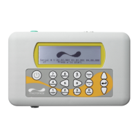
Details the U1000MkII display layout, indicators, and button functions for operation and navigation.
Recommends pipe straight lengths upstream and downstream for optimal flow measurement accuracy.
Explains how to connect power supply and signal cables to the U1000MkII Electronics Module.
Outlines the initial screen sequence and setup prompts for U1000MkII-FM and U1000MkII-HM models.
Guides on adjusting flow sensor positions based on the separation code displayed by the Electronics Module.
Instructions on applying adhesive gel pads centrally onto the bases of the two flow sensors.
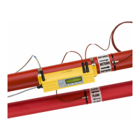
Details on clamping the sensor assembly onto the pipe, including the use of adaptors for different pipe diameters.
Procedure for releasing and removing sensor-holding screws, noting sensors are spring-loaded for contact.
Instructions for connecting the Electronics Module to the Sensor Assembly, emphasizing connection care.
Details on attaching temperature sensors for HM models, including balancing and thermal contact considerations.
Procedure for clipping the Electronics Module onto the Sensor Assembly and securing it with a screw.
Explains the importance of zeroing flow sensors in installed application for accurate readings.
Guides on how to access password-protected menus for changing default settings and navigating options.
Flowchart detailing metric setup options including dimensions, pipe ID, fluid type, and material.
Flowchart outlining imperial setup options like dimensions, pipe ID, fluid type, and material.
Options for resetting volume totals and setting the format for total volume readings.
Configuration settings for the 4-20mA current output, including enabling and flow rate values.
Details pulse output modes like Volume, Energy, Frequency, and Alarm types for U1000MkII-HM models.
Explains calibration procedures including damping time, zero offset, and temperature offset for HM models.
Provides information on diagnostics screens for checking TA, pulse status, errors, firmware, and signal quality.
Describes setup options for pulse output: Volumetric, Energy, Frequency, Low Flow Alarm, and Signal Loss Alarm.
Details the default settings and functionality of the 4-20mA current output, including alarm current.
Ensuring correct pipe diameter entry is crucial for accurate separation distance in configuration.
Verify gel pad covers are removed and sensors are correctly positioned on the pipe with screws fully removed.
Excessive air in the system or an empty pipe can lead to insufficient conditions for meter operation.
Ensure ultrasonic grease or gel pads are correctly installed on the sensor block for proper contact.
Corroded pipe surfaces or internal deposits can distort signals and affect meter performance.
Install unit where fluid flows uniformly, away from disturbances like bends, valves, or pumps.
System isolated or pump off may show flow if zero-flow offset wasn't set during installation.
Low flow rates may show no reading; lowering zero cut-off can help, but check for noise/instability.
Surface roughness of galvanised pipes can affect accuracy and prevent valid flow signal acquisition.
Fluid concentration variations in mixtures like Glycol/Water or Ethanol/Water can cause errors.
Composite pipes show limited compatibility due to signal propagation issues, dimming or misdirection.
Provides detailed technical specifications for the U1000MkII including measurement, output, and environmental parameters.
Lists the factory default settings for metric and imperial units for various parameters like flow units and pipe size.
| Type | Ultrasonic Flow Meter |
|---|---|
| Accuracy | ±1% of reading |
| Enclosure | IP65 |
| Display | LCD |
| Weight | 1.2 kg |
| Technology | Transit Time |
| Outputs | 4-20mA, Relay, RS485 |
| Power Supply | 24VDC or 220VAC |