Do you have a question about the Micronics U3000 and is the answer not in the manual?
Describes the U3000/U4000 flowmeter, its ultrasonic transit time technique, and features.
Explains the ultrasonic transit time technique, modes of operation, and signal path.
Lists and illustrates standard equipment supplied with the U3000/U4000 flowmeter.
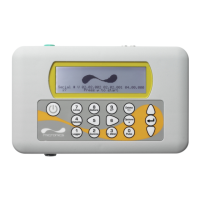
Details the microprocessor-controlled instrument, its display, keypad, and functionalities.
Explains the transducer connections and other interface ports on the instrument.
Describes the U3000 and U4000 keypads and their functions for instrument control.
Covers mains and 24V supply options, and behavior during power failure.
Details optional plug-in modules for the U4000, like Heat Meter and process control.
Provides critical safety warnings related to lethal voltages and IP65 enclosure protection.
Guides on positioning and physically mounting the instrument enclosure.
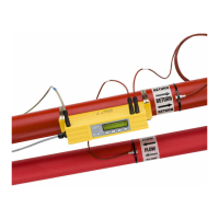
Covers the process of installing the ultrasonic transducers on the pipe.
Guides on installing the necessary driver for U4000 PC communication.
Outlines initial setup steps like language, date, and time configuration.
Guides through entering site data for initial configuration and transducer setup.
Details on fine-tuning the instrument for local conditions and application.
Describes configurable Current, Pulse, and Alarm outputs.
Guides on manually calculating average flow rates over a period.
Steps to set up manual start/stop logging to the instrument's memory.
Guides on setting up timed start/stop logging to memory.
Procedure for logging data directly to a PC via RS232 or USB.
Setting up simultaneous logging to internal memory and a PC.
Steps to download stored data from the U4000 to a PC.
Information on using Micronics' software for data download and analysis.
Instructions for printing logged data using an RS232-compatible printer.
How to operate with the Calec® ST Energy Totaliser for energy measurement.
Provides general guidance on cleaning, cable care, and sensor maintenance.
Critical warning against disassembling the unit without authorization.
Lists potential causes of problems: faulty instrument, incorrect setup, application issues.
A flowchart-based procedure to diagnose and resolve common issues.
Explains various error and warning messages displayed by the instrument.
Describes how to access and interpret diagnostic parameters for advanced troubleshooting.
Lists common optional features like high temp transducers, guide rail options, etc.
Lists options exclusive to the U4000 model.
Provides general specifications like measurement technique, ranges, and accuracy.
Lists suitable fluid conditions and examples for the flowmeter.
Details on compatible pipe materials, dimensions, and linings.
Summarizes standard, high-temperature, and optional transducer sets.
Specifications for the U4000 data logging features.
Lists supported languages and details on serial, current, and pulse outputs.
Details on alarm outputs and power supply specifications.
Details on enclosure, keypad, display, and fixing specifications.
Lists operating/storage limits and compliance standards.
| Type | Ultrasonic Flow Meter |
|---|---|
| Resolution | 0.001 m/s |
| Operating Temperature | -20°C to +60°C |
| Temperature Range | +200°C |
| Outputs | 4-20mA, Pulse, Relay |
| Communication | RS485 |
| Power Supply | 24 VDC |
| Measurement Range | 0.01 to 12 m/s |
| Operating Humidity | 5% to 95% RH |