1: General Description
6 U3000/U4000 User Manual
(Issue 2.0)
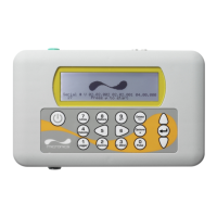
Menus and the menu selection keys
Note: As a security measure, once the instrument has been set-up for the first time a password is required to
gain subsequent access to the operating menus.
The U3000/U4000 menus are arranged hierarchally with the MAIN MENU being at the top level. Menu
navigation is achieved by three keys located on the right hand side of the keypad which are used to scroll UP
and DOWN a menu list and SELECT a menu item. When scrolling through a menu an arrow-shaped cursor
moves up and down the left hand side of the screen to indicate the active menu choice which can then be
selected by pressing the ENTER (SELECT) key.
Some menus have more options than can be shown on the screen at the same time, in which case the
overflowed choices can be brought into view by continuing to scroll DOWN past the bottom visible item. Menus
generally ‘loop around’ if you scroll beyond the first or last items.
If you select Exit on any menu it usually takes you back one level in the menu hierarchy, but in some cases
it may go directly to the ‘Flow Reading’ screen.
Some screens require you to move the cursor left and right along the display as well as up and down. This is
achieved using keys 5 (scroll LEFT) and 6 (scroll RIGHT).
Dual function numerical keypad
The block of keys shown in the centre of the keypad in Figure 1.4
are dual function keys. They can be used to
enter straight-forward numerical data, select the displayed flow units or provide quick access to frequently
required control menus.
1.4.3 Power supply
Mains supply
As standard, the instrument is designed to work with a mains supply of 86-236V and 50/60Hz. A 500mA
mains supply fuse is located adjacent to the mains power connection (see Figure 2.3).
24V Supply
An alternative 24V a.c./d.c. power supply module is available as a factory (distributor) fitted option. This
supply is protected by a resettable solid-state fuse located on the U3000/U4000 motherboard. If this fuse
opens it can be reset by isolating the 24V supply.
Power failure
The instrument will automatically power-up and become operational when the input power is applied. In the
event of a power failure the instrument’s configuration parameters are stored in non-volatile memory, which
then allows the instrument to return to normal operation immediately power is restored.
On the U4000 a real time clock (RTC) records the date/time of any power disruptions and time-stamps any
such occurrence in the output log. All data logging ceases while power is unavailable.
1.4.4 Expansion modules (U4000 only)
The U4000 motherboard contains a standard plug-in communications module which provides RS232 and
USB functions. An expansion slot is available which can be used to extend the functionality of the U4000 to
include a Heat Meter or a range of process control interface options through a plug-in expansion module.
Details of available plug-in modules and other optional equipment are given in Chapter 7.