1: General Description
4 U3000/U4000 User Manual
(Issue 2.0)
U3000/U4000 Optional equipment
• High temperature transducer sets ‘A-HT’ and ‘B-HT’ (-20°C to +200°C).
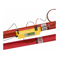
• Transducer set 'D' - used for monitoring pipes of 1500mm to 5000mm diameter, over a temperature
range -20°C to +80°C. This kit is supplied in a separate case and includes the sensors together with
ratchet straps and guide rails for attaching to the pipe.
U4000 Optional equipment
• Heat Meter: This option allows the U4000 to calculate the heat energy between an inlet and outlet
pipe at different temperatures for a given flow rate. It comprises a plug-in board that performs the
energy calculation. This option requires two sets of Pt100 4-wire temperature probes.
• Process Control Busses: The first of these to be offered will be the MODBUS protocol using EIA/RS-
232 or EIA/RS-485 physical layer.
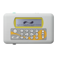
1.4 U3000/U4000 Instrument
The U3000/U4000 is a microprocessor controlled instrument operated through a menu system using an
inbuilt LCD display and keypad. It can be used to display the instantaneous fluid flow rate or velocity, together
with totalised volumes. The instrument can also provide an isolated current output, or variable pulse output,
proportional to the measured flow rate which can be scaled to suit a particular flow range. Finally, two
isolated alarm outputs are provided which can be configured in a number of ways. For example, to operate
when the flow rate exceeds a specified maximum or minimum limit.
In addition, the U4000 can function as a data logger. When operating in this mode the logged data can be
output to the instrument's memory, to a PC (via the RS232 or USB serial interfaces), or simultaneously to
both memory and PC. When logging to memory only, the logged data can be downloaded to the PC at a later
time. Both the flow rate and +/- Totals can be logged, with up to 96K logging events stored internally.
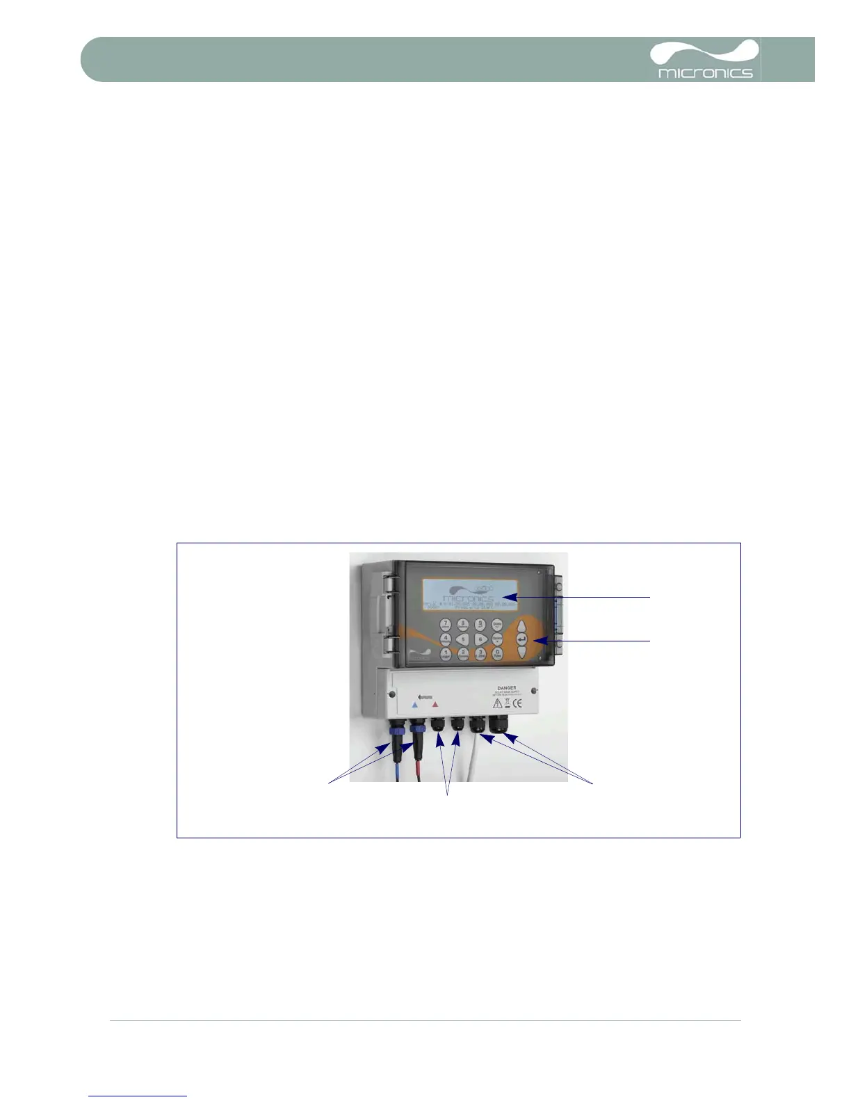
1.4.1 Connections
Figure 1.3 Instrument details
Transducer connections
The transducer probes are connected to two coaxial sockets located on the bottom left-hand of the
instrument. The silk-screen above these connectors show a red and blue triangle and a direction of flow
symbol. For a positive flow reading, it is important that the upstream transducer is connected to the RED
socket and the downstream transducer to the BLUE one. It is safe to connect or disconnect the cable while
the instrument is switched on.