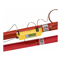
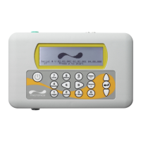
1: General Description
U3000/U4000 User Manual 5
(Issue 2.0)
USB connection (U4000 only)
A USB cable is supplied as part of the U4000 kit and can be connected between the U4000 instrument and a
PC to download logged data. The USB connector, located on the top left hand side of the flowmeter as
shown in Figure 2.2
, uses a Bulgin screwed type connector to preserve the enclosure’s IP 65 rating.
RS232 Connection (U4000 only)
An RS232 cable is supplied as part of the U4000 kit to allow communications with a PC or printer. The RS232
cable can be inserted through one of the Alarms & I/O cable glands as shown in Figure 2.2
.
4-20mA, ‘Pulse’, and Alarm I/O connections
The 4-20mA, ‘pulse’, and alarm I/O cables enter the bottom of the instrument via two cable glands and are
connected internally to a terminal block. Full details of the terminal connections are provided in Chapter 2
(Installation) and Chapter 7 (Options).
Power supply
Two cable glands on the bottom right-hand side of the instrument are available for the power supply cable.
Two sizes of glands are provided to accept cables of different diameters.
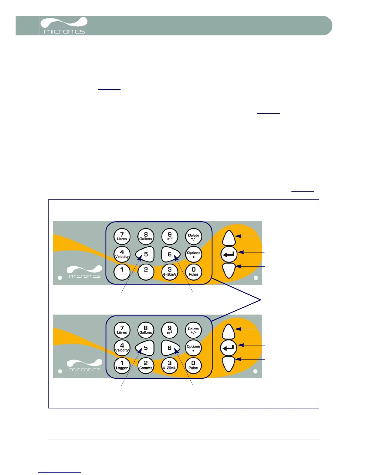
1.4.2 Keypad
The instrument is configured and controlled via a 15-key tactile membrane keypad, as shown in Figure 1.4.
Figure 1.4 U3000/U4000 Keypad