3: Operating Procedures
22 U3000/U4000 User Manual
(Issue 2.0)
3.3.3 Adjusting the calibration factor
With the system running:
1. Stop (Stall) the totaliser facility and zero it (Paragraph 3.5
).
2. Run the totaliser to measure the total flow over a 30-60 minute period, and note the total flow indicated by
the reference flow meter over the same period.
3. Calculate the % error between the U3000/U4000 instrument and reference meters. If the error is greater
than ±1% calibrate the U3000/U4000 as detailed below.
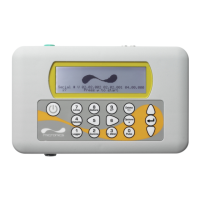
4. Press the Options key to access the
FLOW READING OPTION screen shown.
5. Scroll down and select Calibration
factor then press ENTER.
6. Change the calibration factor according to
the error calculated in step 3. For example,
if the instrument was reading 1% high then
increase the Calibration factor value
by 0.010. Conversely, if the reading is 1%
low then decrease the calibration factor to
0.990.
7. Press ENTER to apply the change.
8. Select Roughness factor or Exit as
required and press ENTER.
3.3.4 Adjusting the roughness factor
The roughness factor compensates for the condition of the internal pipe wall, as a rough surface will cause
turbulence and affects the flow profile of the liquid. In most situations it is not possible to inspect the pipe
internally and the true condition is not known. In these circumstances experience has shown that the
following values can be used:
Key Point: USE THIS FACILITY WITH CARE & ONLY WHERE NECESSARY
The instrument is fully calibrated before leaving the factory and under normal cir-
cumstances does not require further calibration when used on site.
This facility can be used to correct the flow indication where unavoidable errors occur
due to the lack of a straight pipe or where the sensors are forced to be fitted close to
the pipe-end, valve, junction etc.
Any adjustment must be made using a reference flowmeter fitted in the system.
Pipe Material Roughness
Factor
Pipe Material Roughness
Factor
Non ferrous metal
•Glass
• Plastics
•Light metal
0.01 Welded steel pipes, new:
• Long usage, cleaned
• Lightly and evenly rusted
• Heavily encrusted
0.1
Drawn steel pipes:
• Fine planed, polished
surface.
• Plane surface
• Rough planed surface
0.01 Cast iron pipes:
• Bitumen lining
• New, without lining
• Rusted / Encrusted
1.0
FLOW READING OPTION DD-MM-YY HH:MM:SS
Data review
Zero Cutoff (m/s) : 0.010
Set zero flow (m/s) : 0.000
Damping (secs) : 10
Totaliser : Run
Reset +Total
Reset –Total
Calibration factor : 1.000
Roughness factor : 0.010
Alarm Settings :
Max Pulse Freq (Hz) : 10.00
Flow at Max Frequency : 200.00
Calculated Pulse Value: 2.00
Diagnostics
Exit