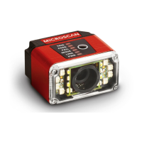
MicroHAWK ID Accessories
MicroHAWK ID Part Numbers
MicroHAWK ID part numbers follow the format 7ABX-YZZZ-LPPP.
7 = MicroHAWK.
(A) Model
1: Engine, No Case, USB
2: ID-20, IP40 Case, USB
3: ID-30, IP54 Case, 5V, USB
4: ID-40, IP65 Case, 24V, Ethernet
(B) Software
1: Auto ID
(X) Sensor
1: WVGA, 0.3 Megapixel, Mono
2: SXGA, 1.2 Megapixel, Mono
3: QSXGA, 5 Megapixel, Color
(Y) Optics
0: Custom
1: Standard Density
2: High Density
(ZZZ) Focus Distance
050: 50 mm = 1.96 in.
064: 64 mm = 2.51 in.
081: 81 mm = 3.18 in.
102: 102 mm = 4.02 in.
133: 133 mm = 5.23 in.
190: 190 mm = 7.48 in.
300: 300 mm = 11.81 in.
(L) Outer LED Color
0: N/A (Engine and ID-20)
1: Red
2: White
(PPP) Speed and Decoder
000: Standard Speed
001: High-Speed
002: 1D/2D Decoder
003: X-Mode Decoder
004: High-Speed 1D/2D Decoder
005: High-Speed X-Mode Decoder
Mounting Options
Adapter Plate Kit 98-9000034-01 MicroHAWK to MINI Adapter Plate Kit
Software and Documentation
Microscan Tools Drive 37-000010-01 Software, documentation, links to Microscan website
Note: Additional accessories are available in the Microscan Product Pricing Catalog.
Power Requirements and Pin Assignments
MicroHAWK ID-20: 5VDC ± 5%; 350mA at 5VDC (typ.)
MicroHAWK ID-30: 5V ± 5%; 600mA at 5VDC (typ.)
MicroHAWK ID-40: 4.75V – 30V; 150mA at 24VDC (typ.)
ID-20 Micro-USB Type B Socket Connector
Pin Function
1 Vbus (5V)
2 D–
3 D+
4 N/C
5 Ground
ID-30 15-Pin High-Density Dsub
USB/Serial Socket Connector
ID-40 M12 Connectors
Pin Function
1 +5VDC
2 TX232
3 RX232
4 GND
5 D+
6 N/C
7 Output 1+
8 Default+
9 Trigger+
10 D–
11 Output 3+
12 New Master+
13 Chassis
14 Output 2+
15 Vbus
TX (+)
RX (–)
RX (+)
TX (–)
Terminated
Terminated
M12 8-pin Socket (Ethernet)
Terminated
Te rm i na t ed
Ground
Output 3
Output 1
Output 2
New Master
Default
Power
Input Common
Output Common
RS-232 (Host) RxD
Trigger
RS-232
(Host) TxD
M12 12-pin Plug
Note: Accessory
cable required
between 15-pin
socket and host
USB port.
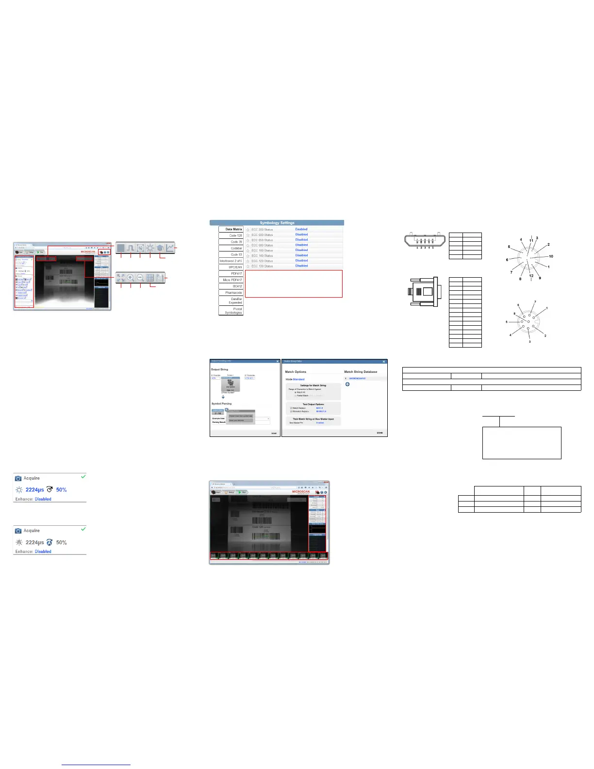
Step 12 — Configure Symbology Settings
Clicking the gear icon at the bottom of the Decode dialog brings up Symbology Settings. This allows
you to configure every parameter for every available code type.
Data Matrix error correction parameters are
shown in this example, but you can configure any
parameter for any of the code types supported by
WebLink. All parameter changes for all code types
take effect immediately.
Step 9 — Explore the Setup View
The Setup View allows you to configure all aspects of a setup. The left pane of the UI gives you the
ability to configure Cycle type, Acquire, Decode, Match String, Format Output, and Outputs 1, 2,
and 3 parameters.
Clicking the Save icon in the upper right of the interface saves current settings to the reader’s flash
memory so the settings will be available when the reader is rebooted.
The question mark icon in the upper right of the interface opens WebLink Help.
The gear icon in the upper right of the interface brings up Application Settings.
Start
and
Stop
Trigger
WOI
Auto
Photometry
Optimize
Train
Resize
image to
fit image
area
Zoom
In
Zoom
Out
Show All
Images from
Read Cycle
Save full-size
image
Step 10 — Configure Read Cycle Settings
The Cycle section of the Setup View allows you to modify the trigger, determine the number of symbols
for the reader to expect, and set Read Cycle Timeout. A dropdown menu of various Cycle types provides
a variety of options, each with configurable parameters.
Presentation
This mode, commonly referred to as “hand presentation mode”, uses Continuous Trigger along with
Continuous Capture Mode and a Timeout at End of Read Cycle. Green Flash Mode is set to Static
Presentation and the Green Flash Duration is set to 1 second.
Continuous
This mode allows you to set the Read Cycle Timeout and the expected number of symbols.
Triggered
This mode sets the Read Cycle to Serial Data and Edge, End of Read Cycle is set to Timeout or New
Trigger, and Capture Mode is set to Rapid Capture with 1 capture. You can adjust the Serial Trigger,
Trigger Delay, Timeout, and Number of Symbols.
Start / Stop
This mode uses External Level with a Read Cycle Timeout and Continuous Capture, allowing you to
set Leading Edge and Trailing Edge as well as the Serial Trigger and the Start and Stop Characters.
Custom
This mode allows you a wider variety of read cycle scenarios. Use this mode to select Trigger mode and
to set Serial Trigger Character and Trigger Delay; to select Capture Mode and to set Number of
Captures, Rapid Capture Mode, and Delay between Images; and to select the End Cycle On setting
as well as Timeout and Number of Symbols.
Step 11 — Configure Acquire Settings
Acquire settings allow you to set Exposure (signified by the sun icon) and Gain (signified by the dial
and right-pointing arrow icon) in real time. Clicking any of these settings will cause a control to appear,
allowing you to modify that setting. Settings take effect immediately.
When Auto Photometry is enabled instead of Standard, Exposure and Gain are read-only. The A
shown on the sun and dial icons signifies that Auto Photometry is enabled. Auto Photometry constantly
determines the best Exposure and Gain settings during each read cycle.
Step 13 — Format Output and Match String
Format Output, when enabled in the Setup View, allows you to determine the many ways in which
barcode data can be formatted and parsed before it is output as a data string. You can also set Preamble
and Postamble in this dialog.
Match Options and Match String Database, accessible by clicking the Match String section in the
Setup View, allow you to set the match code mode, text output, new master, and match string database.
Step 14 — Run the Application
In the Run view, you can observe the progress of the setup as it follows the parameters you have
defined. The right panel of the UI shows Counts for Cycles, Reads, No Reads, and Mismatches, as
well as Rate information for Capture, Decode, Overhead, Total Read, and Trigger Rate, as well as
Output Data. A "filmstrip" below the image area shows each image capture with a green check mark
for good reads and a red x for no reads.
Example Part Number:
7312-2102-1005
MicroHAWK ID-30, Auto ID, SXGA 1.2
Megapixel, Mono, High Density, 102 mm
Focus Distance, Red Outer LEDs, High
Speed X-Mode Decoder.
Sensor Table
Pixels (H x V) Shutter
Frames per Second
(Standard / High)
WVGA 752 x 480, 0.3 MP, Mono Global 10 fps / 60 fps
SXGA 1280 x 960, 1.2 MP, Mono Global 10 fps / 42 fps
QSXGA 2592 x 1944, 5 MP, Color Rolling 5 fps
 Loading...