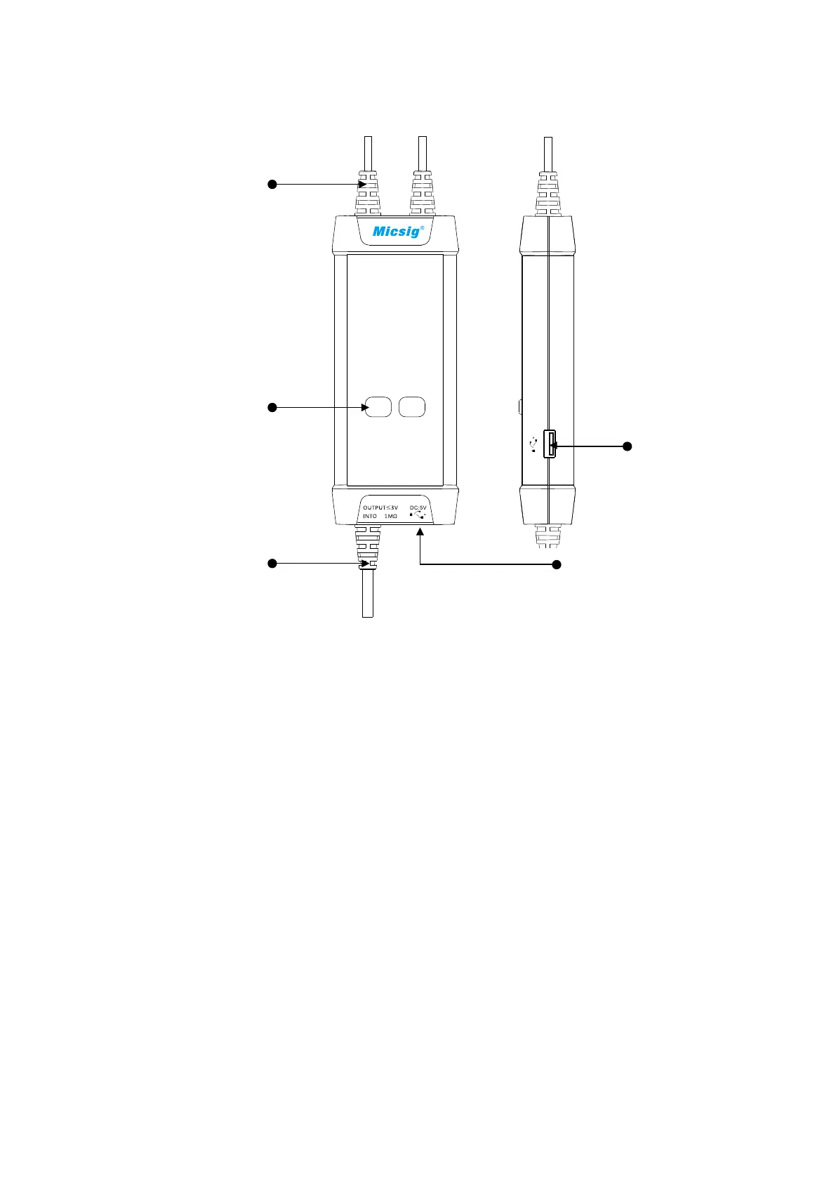
Panel Description
Signal Input
Attenuation Range
Buttons/Indicators
(Over-range if flashing)
Signal Output Power Input
Power Output
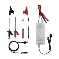
Making Measurements
Connect the USB input of the probe to the USB port of the oscilloscope
or a suitable USB power source.
4
3
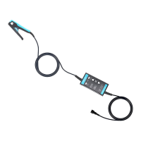
1) Powering the probe:
2) Connecting the probe to the oscilloscope:
Connect the probe output BNC to the oscilloscope channel input.
Note: make sure the oscilloscope is properly grounded if necessary.
3) Set the appropriate attenuation range according to the measured
voltage.
4)
Connecting the input to the device under test:
Using the appropriate input accessory, connect the probe to the device
under test to start the measurement. If the attenuation range indicator
flashes (indicating over-range), please immediately disconnect the
power and input.
5) Set the measuring instrument.