Rise Time
Maximum Differential
Test Voltage
(DC+AC PK-PK)
Maximum input
common mode voltage
Input referred noise
Common Mode
Rejection Ratio
Input Impedance
Output Voltage
Overrange Alarm
Input cable length
Output cable length
Model
Bandwidth
Attenuation
Gain accurecy
Power Supply
Power
Dimension
≤160mVrms(200X)
≤920 mVrms(2000X)
50MΩ/1.25pF( )
25MΩ/2.5pF(single-ended
to ground)
differential
DP20003
100MHz
3.5ns
200X
2000X
±2%
560V (200X)
5600V (2000X)
>80dB(DC)
>60dB(100KHz)
>50dB(1MHz)
≤3V
Button light flashes
DC 5V,USB Supply
0.85W
14.5cm*6cm*2.7cm
Approx 45cm
Approx 90cm
0℃~40℃
10%~85% RH
≤40mVrms(50X)
≤230 mVrms(500X)
10MΩ/1pF(differential)
5MΩ/2pF(single-ended
to ground)
DP10013
100MHz
3.5ns
50X
500X
±2%
130V (50X)
1300V (500X)
CAT 1000V
>80dB(DC)
>60dB(100KHz)
>50dB(1MHz)
≤3V
Button light flashes
DC 5V,USB Supply
0.85W
14.5cm*6cm*2.7cm
Approx 45cm
Approx 90cm
0℃~40℃
10%~85% RH
CAT 1000V
II
III
Please read this manual carefully before use!
Introduction
The Micsig DP series of high voltage differential probes are designed for
the safe measurement of high voltage and floating voltage signals. Two
models with 100MHz bandwidth are available, each capable of two different
attenuation ranges: 500X(2000X) for a maximum test voltage of 1300V
(5600V) and 50X(200X) for amaximum test voltage of 130V(560V).
1
2
Specification
Operating Humidity
Operating
Temperature
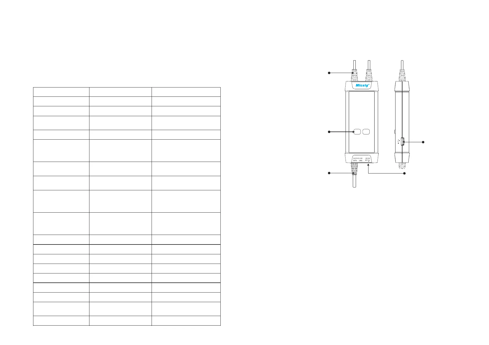
Panel Description
Signal Input
Attenuation Range
Buttons/Indicators
(Over-range if flashing)
Signal Output Power Input
Power Output
Making Measurements
Connect the USB input of the probe to the USB port of the oscilloscope
or a suitable USB power source.
4
3
1) Powering the probe:
2) Connecting the probe to the oscilloscope:
Connect the probe output BNC to the oscilloscope channel input.
Note: make sure the oscilloscope is properly grounded if necessary.
3) Set the appropriate attenuation range according to the measured
voltage.
4) Connecting the input to the device under test:
Using the appropriate input accessory, connect the probe to the device
under test to start the measurement. If the attenuation range indicator
flashes (indicating over-range), please immediately disconnect the
power and input.
5) Set the measuring instrument.
 Loading...