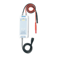
High Voltage Differential Probe
User Manual
DP10013/DP20003
General Usage Summary
Connecting the probe: First, connect the probe's USB power input to a USB
power source such as the oscilloscope's USB port and connect the probe's BNC
connector to an oscilloscope input. Then, set the proper attenuation rate and
connect the probe input to the device under test.
Only qualified personnel should perform service on this product.
Do not touch exposed connections and components when power is present.
Disconnecting the probe: First, disconnect the probe inputs from the device
under test, and then unplug the probe output and power input.
Use proper grounding: To avoid an electric shock, all devices that require
grounding must be connected to earth ground. Before making connections to
the input or output terminals of the probe, ensure that the test instrument is
properly grounded if necessary.
Measurement safety: Always be aware of the voltage rating of the probe and
the measurement accessories you are using and of the maximum amplitude of
the signal you intend to measure. Never apply a potential that exceeds the
voltage ratings of the probe and/or its accessories to avoid damaging the
product and creating a hazardous situation.
Do Not Operate in an Explosive Atmosphere.
Do Not Operate in Wet/Damp Conditions.
Keep Product Surfaces Clean and Dry.
If an over-range condition occurs, please disconnect power and signal input
from the probe immediately.
2) Extending the input leads may introduce more noise during measurement.
If extra extension lead is necessary, please ensure the extension leads
are of equal length and the input signal frequency is under 10MHz.
Otherwise, measurement errors may occur.
Warranty
6
Micsig warrants that this probe will be free from defects in materials and
workmanship for a period of one (1) year and accessories for a period of
six(6) months from the date of shipment. If any such product proves
defective during this warranty period, Micsig, at its option, either will repair
the defective product without charge for parts and labor, or will provide a
replacement in exchange for the defective product. Parts, modules
and replacement products used by Micsig for warranty work may be new
or reconditioned to like new performance. All replaced parts, modules and
products become the property of Micsig.
Shenzhen Micsig Instruments Co., Ltd.
Add: 305 Block A, CLOU Building, Baoshen RD, North Area, Nanshan
Science & Technology Park, Shenzhen, Guangdong, China. 518000
WEB: www.micsig.com
TEL: +86-755-88600880
E-mail: sales@micsig.com
3) While measuring a high frequency signal, don't touch the end of the
input lead with your hand or other objects. Otherwise, it may affect
the accuracy of the measurement.
4) Ensure that you use an oscilloscope with an input impedance of at
least 1MΩ and bandwidth of at least 100MHz.
5) Turn on the oscilloscope or externally powered instrument and let
the probe and equipment warm up for 20 minutes.
Best Practices:
5
1) Twisting the input leads together can help reduce noise and improve
the probe's high frequency response when measuring signals. Please
view the diagram below for an example:
6) When a substantial change in temperature or other circumstances affect
the accuracy of the probe's zero point, a calibration is needed: short the
input terminals of the probe, then power the probe while simultaneously
pressing the 50X(200X) and 500X(2000X) keys for three seconds.
Gift