4.WIRECONNECTIONOFINDOORUNITANDOUTDOORUNIT
WARNING:Beforeperforminganyelectricalwork,unplugtheunitandturnoffthemainpowertothesystem
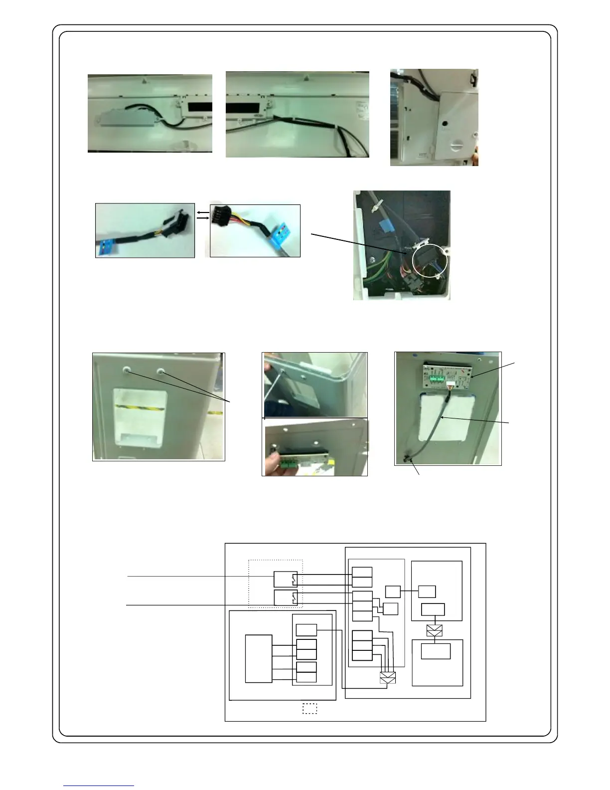
1.TheDRcontrolboxhasbeeninstalledandconnectedwiththeindoorunitasshowninFig.2.
2.Remove cover of the electrical control box of indoor unit by loosening the screw. Inside there is a connector which can be connected with the
DR connective wire A(9m) , as shown in Fig.3.
3.The outdoor DR board is installed at the back of the right-side plate of outdoor unit, fixed by two screws as shown in Fig. 4 (the DR board is installed on
the plate horizontally or vertically (model dependent). First remove the top cover and then take down the DR board by loosening the screws from outside
of the outdoor unit. Using the DR connective wire B(250mm), connect to the DR board with the DR connective cable A(9m). Then connect the DR board
with DCSR as shown in Fig.5. After connection, reinstall the DR board on the right-side plate with the original two screws.
Fig.2
Fig.3
Fig.4
Fig.5
Connectorofindoorunit
Screws
DRboard
DRconnective
wireB
(250mm)
Right-sideplateofoutdoorunit
(frontview)
Loosenthescrewsandtakethe
DRboarddown(backview)
ConnecttotheDRconnective
cable A(9m)
ConnectorofDR
connectivewireA(9m)
Operationstate:
Open:IndoorunitON
Close:IndoorunitOFF
Operationstate:
Open:Indoorunitforced OFF
Close:IndoorunitON
NOTE:Thissymbolindicatestheelementisoptional,theactualshapeshallprevail.
OUTDOORUNITDRBOARD
ON/OFF1
DRM3
DRM2
DRM1
COMMON
Government
A/CController
(DCSR)
PURPLE
PINK
GRAY
ORANGE
ON/OFF2
SWITCH2
SWITCH1
MAINBOARD
USER
SWITCH
USER
SWITCH
INDOORUNIT
CN4
CN3
CN2
OPTIONAL
DISPLAYBOARD
CN301
CN201
CN201
CN42
Government
A/CController
(DCSR)
DRM3
DRM2
DRM1
OUTDOORUNIT
DRM3
DRM2
DRM1
DRM3
DRM2
DRM1
CN904
COMMON
CN903
CN902
YELLOW
WHITE
RED
BROWN
DRBOARD
CN5OR
CN10ORCN10A
4. Wiring diagram of indoor unit and outdoor unit, Fig5. For more details, please refer to the Installer's Manual of the Demand Control
Signal Receiver supplied by Electric Power Company..
 Loading...