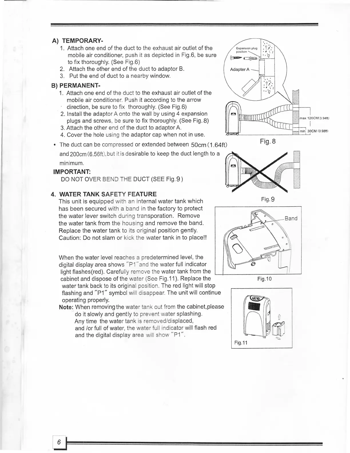
A) TEMPORARY-
1.
Attach one end
of
the duct to the exhaust air outlet of the
mobile air conditioner, push it
as
depicted
in
Fig.6,
be
sure
to fix thoroughly.
(See Fig.6)
2. Attach the other end
of
the duct to adaptor
B.
3.
Put the end of duct to a nearby window.
S) PERMANENT-
1.
Attach one end
of
the duct to the exhaust air outlet of the
mobile air conditione
r.
Push it according to the arrow
direction,
be
sure to fix thoroughly. (See Fig.6)
2.
Install the adaptor A onto the wall by using 4 expansion
plugs and screws,
be
sure to fix thoroughly. (See Fig. 8)
3.
Attach the other end of the duct to adaptor
A.
4. Cover the hole
us
ing
th
e adaptor cap when not
in
use.
• The duct can
be
compressed or extended between
SOem
(1.64ft)
and
200cm (6.56ft
),
bu
t i is desirable to keep the duct length to a
minimum.
IMPORTANT:
DO
NOT OV
ER
BE
0 THE DUCT (SEE Fig. 9 )
4. WATER TANK SAFETY FEATURE
This unit is equipped with an internal
water
tank which
has been secured with a band in the factory to protect
the
water
lever switch
dur
ing transporation. Remove
the
water
tank from the housing and remove the band.
Replace the
water
tank to i s original position gently.
Caution: Do n
ot
slam
or
kick he
water
tank
in
to place!!
When the water level reaches a predetermined level, the
digital display area shows
"p "and the water full indicator
light flashes(red).
Carefully
re
ove
th
e water tank from the
cabinet and dispose
of
the wa er (See Fig.11). Replace the
water tank back to its original positi
on
. The red light will stop
flashing and
"P1"
symbol will disappear. The unit will continue
operating properly.
Note: When removing the water a out from the cabinet, please
do
it
slowly and gently to prevent water splashing.
Any time the water tank is removed/displaced,
and
lor
full of water, the wate fu
ll
indicator will flash red
and the digital display area wi
ll
show "
P1
".
ExpansIon plug
pos
iti
on
Fig.11
Fig.8
Fig.9
Fig.10
 Loading...