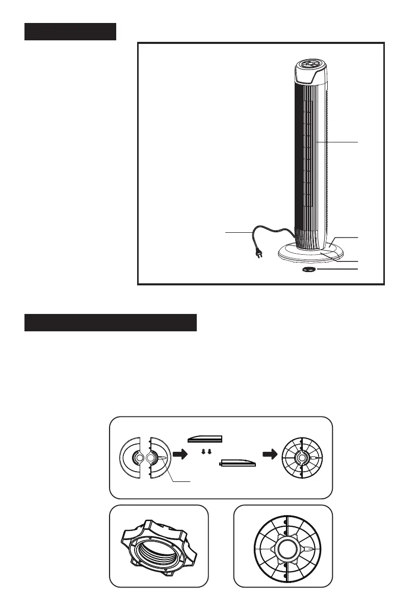
PART FIGURE
Note: All the pictures in this manual are for explanation purpose only. Any discrepancy between
the real object and the illustration in the drawing shall be subject to the real subject.
1. Body
2. Rear base
3. Front base
4. Plastic nut
5. Power cord
ASSEMBLY INSTRUCTIONS
1
3
4
2
5
The outlet through
Fig.1
Fig.2 Fig.3
1. Take out the fan body and the spare parts from the box. Put the front base onto
rear base and join them together. (See Fig. 1)
2. Unlock the plastic nut from the fan body.
3. Pass the power cord through the flute, then insert the fan body into the base.
(See Fig. 3)
4. Fix the fan body on the base with the plastic nut. (See Fig. 2)
3

 Loading...