1
2
3
4
11
22
33
22
22 22
22
22
33
33
33
33
33
33
33
11
33
33 33 33
11
22
22 22 22
33 33
33 33
33
33
11
22
33
33
33
Mode
Qty. of
indoor unit
(Air-in )
(Air-out )
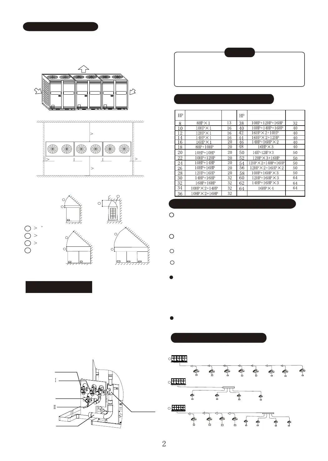
Outdoor unit planform
Installation and maintenance surface
1000mm
1000mm
20mm~ 500mm
1000mm
1000mm
2. When there is obstacle above the outdoor unit:
A
B
C
D
45
1000mm
Airflow deflector
Front view
B
A
B
A
C
D
Side view
B
A
20mm~ 500mm
INSTALLATION SPACE
1. Leave enough space for maintenance (see following
picture) and install power unit on the side of outdoor
unit. Refer to power unit installation manual.
2. Keep the modules in one system at the same level.
(Air-in )
300mm
Front view
Front view
NOTE: The top of any pile around the outdoor unit should at least 800mm
below the top of unit. If not, please install mechanical air discharge equipment.
REFRIGERANT PIPE
1. Refrigerant piping connection is inside the outdoor
unit, please remove the front clapboard.
2. The piping can be led through the down-left of the
outdoor unit or the soleplate gap.
3. When through the front, piping is led by wiring from
the panel, then connect branch pipes towards left
or right.
4. When through the soleplate gap, install the branch
pipe towards left, right or back.
To liquid side pipe
5. If through the front, please remove the clapboard
at corresponding place first.
To prevent the inside of piping from oxidizing
when welding, it is necessary to charge nitrogen,
or oxide may block the circulation.
CAUTION
OUTDOOR UNIT COMBINATION
Mode
Qty. of
indoor unit
SELECT SIZES OF REFRIGERANT PIPES
Refer to table 1 for outdoor unit pipe sizes.
Select branch joint
Select the joint according to the total designed
capacity of indoor units which it connects to. If this
capacity is more than that of the outdoor unit, then
select the connection according to the outdoor unit.
The selection of branch header depends on
the quantity of branches it connects to.
Pipe between outdoor unit and the first
branch (Main pipe)
Size of main pipe connecting multi-modules
See table 2
Pipe between branches
See table 3
Pipe between branch and indoor unit
See table 4
PIPE SIZE AND CONNECTION
(See table 3)
Outdoor unit
Outdoor unit
Outdoor unit
To gas balance pipe
(flaring nut)
To gas balance pipe
(welding)
To oil balance pipe
To gas side pipe
Low-pressure
ball valve
NOTE: No connection
with gas and oil balance
pipes for single module.