M thermal Split
Midea M thermal Split
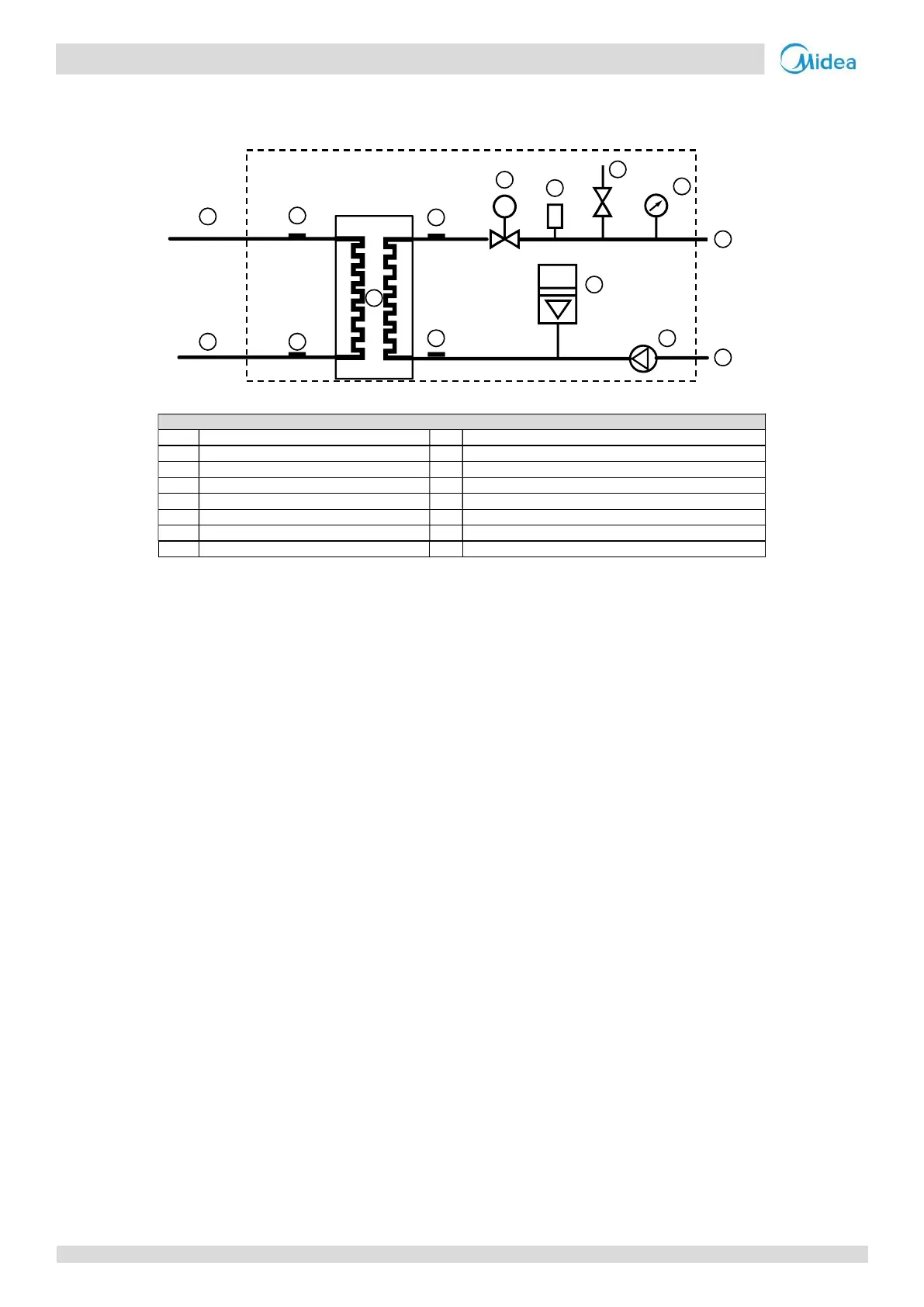
2.2 Hydronic box Piping
Figure 2-2.2: Hydronic box piping diagram
Legend
1 Water side heat exchanger 9 Water pump
2 Water flow switch 10 Manometer
3 Refrigerant liquid line temperature sensor 11 Safety valve
4 Refrigerant gas line temperature sensor 12 Refrigerant gas side
5 Water outlet temperature sensor 13 Refrigerant liquid side
6 Water inlet temperature sensor 14 Water outlet
8 Expansion vessel
Key components:
1. Air purge valve:
Automatically removes air from the water circuit.
2. Safety valve:
Prevents excessive water pressure by opening at 43.5 psi (3 bar) and discharging water from the water circuit.
3. Expansion vessel:
Balances water system pressure. (Expansion vessel volume: 8L.)
4. Water flow switch:
Detects water flow rate to protect compressor and water pump in the event of insufficient water flow.
5. Backup electric heater:
Provides additional heating capacity when the heating capacity of the heat pump is insufficient due to very low
outdoor temperature. Also protects the external water piping from freezing.
6. Manometer:
Provides water circuit pressure readout.
7. Water pump:
Circulates water in the water circuit.
1
2
3
4
5
6
7
8
10
11
12
13
15
9
14
F
14 202004
Midea CAC
 Loading...