M thermal Split
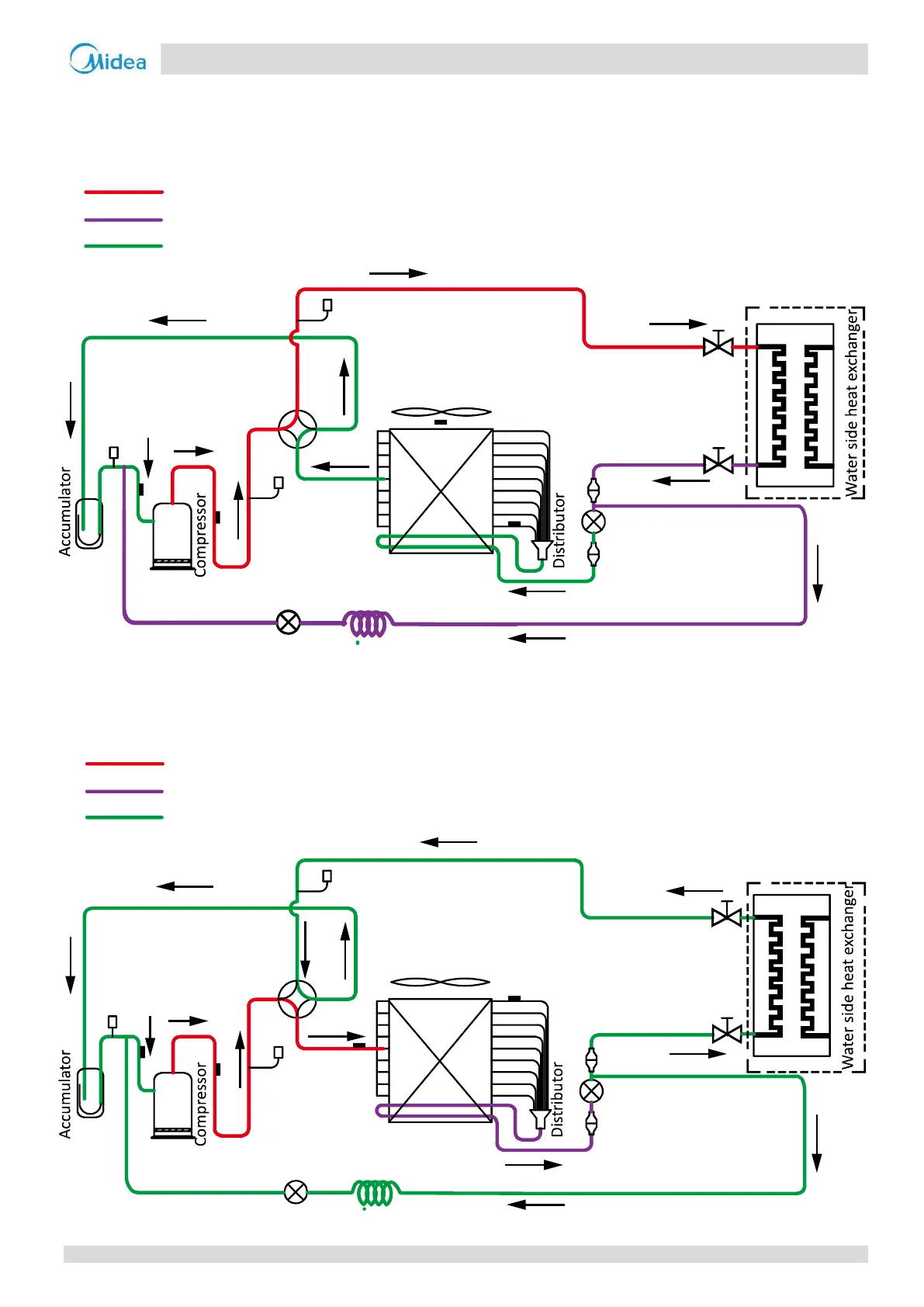
3 Refrigerant Flow Diagrams
Heating and domestic hot water operation
Figure 2-3.1: Refrigerant flow during heating or domestic hot water operation
Cooling and defrosting operation
Figure 2-3.2: Refrigerant flow during cooling and defrosting operations
Pressure sensor
Filter
Electronic expansion valve
Filter
High pressure
switch
Low pressure
switch
Air side heat exchanger
4-way
valve
High temperature, high pressure liquid
Low temperature, low pressure
Electronic expansion valve
capiiiary
Hydronic box
Stop valve
Stop valve
Pressure sensor
Filter
Electronic expansion valve
Filter
High pressure
switch
Low pressure
switch
Air side heat exchanger
4-way
valve
High temperature, high pressure liquid
Low temperature, low pressure
Electronic expansion valve capacity
Stop valve
Stop valve
Hydronic box
202004 15
Midea CAC
 Loading...