M thermal Split
48 202004
Midea M thermal Split
2.4 Digital Display Output
Table 4-2.9: Digital display output in different operating states
M thermal Split system state
Parameters displayed on outdoor
unit main PCB DSP1
Parameters displayed on hydronic
box main PCB DSP1
On standby 0 0
Normal operation
Running speed
rotations per second
Leaving water temperature (°C)
Error or protection Error or protection code Error or protection code
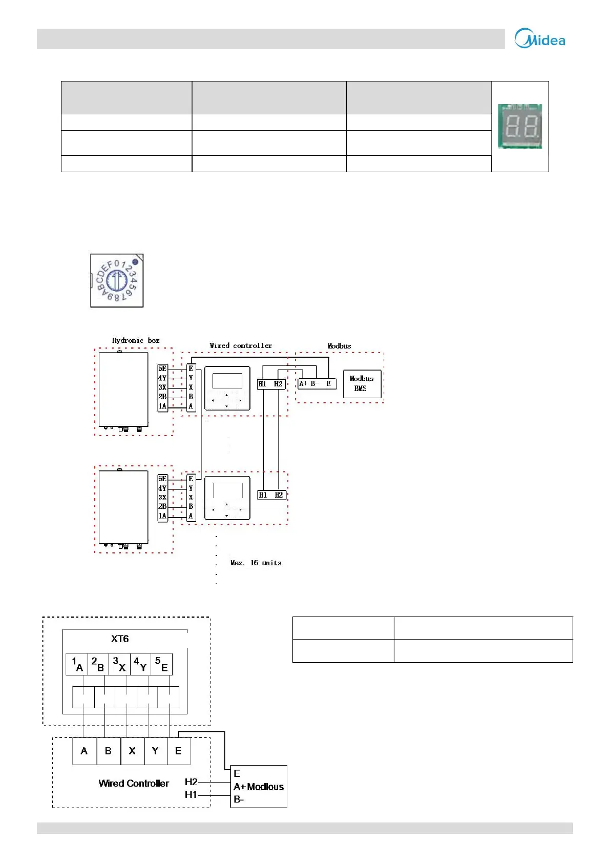
2.5 DIP switch setting and Modbus function (Modbus function will be available in 2020-5-30)
The rotating coded switch S3(0-F) on the main control board of hydraulic module is used for setting the modbus
address. By default the units have this coded switch positioned=0, but this corresponds to the modbus address 16, while
the others positions corresponds the number, e.g. pos=2 is address 2, pos=5 is address 5.
Figure 4-2.10: Rotating switch
Figure 4-2.11: Connection
Note: Wired controller is integrated
Figure 4-2.12: Wiring
Input Voltage(A/B)
13.5VAC
Wiring size 0.75mm²
Midea CAC
 Loading...