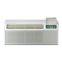
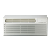
This document is a service manual for the Midea PTAC Series air conditioner, covering models with cooling capacities from 7,000 to 15,000 BTU/H. It provides comprehensive information on the unit's installation, operation, maintenance, and troubleshooting.
Function Description
The Midea PTAC Series air conditioner is designed for both cooling and heating operations, functioning as a consumer air conditioner rather than a refrigerating system for preserving foods or works of art. It features various operational modes and controls to manage room temperature and fan speed. The unit can be controlled via a front panel, a wired wall thermostat, or a wireless module.
Operational Modes:
- Cooling: The compressor and fan operate to cool the room.
- Heating: The unit can operate in heat pump mode or with electric heaters to warm the room.
- Fan-only: The fan operates without cooling or heating, circulating air.
Control Features:
- Temperature Setting: Users can set the desired temperature within a range of 62°F – 86°F (17°C – 30°C).
- Fan Speed: Adjustable fan speeds include HIGH, MED, and LOW.
- Control Panel: The unit features a control panel with buttons for POWER, MODE, FAN, and temperature adjustment (+/-).
- Wired/Wireless Digital Wall Stat: The unit supports external wired thermostats or wireless modules for remote control.
- Front Desk Switch Panel: Allows for centralized control of multiple PTAC units, common in hospitality settings.
Protection Functions:
- Compressor Protection: Includes a 3-minute delay for compressor startup to prevent short cycling and ensure a minimum run time.
- Sensor Protection: Detects open or short circuits in temperature sensors.
- Evaporator Anti-freezing Protection: Prevents the evaporator from freezing in cooling mode.
- High Temperature Protection: For the evaporator in heat pump and cooling modes.
Important Technical Specifications
Cooling Capacity: 7,000-15,000 BTU/H.
Electrical Specifications:
- Input Voltage: 265V, 60Hz; 230/208V, 60Hz.
- Power Connection Options:
- 15A, 20A, 30A for 208/230V.
- 15A, 20A, 30A for 265V.
- 15A for 115V.
- Specific power supply kits (e.g., 6-15P, 6-20P, 6-30P, 7-20P, 7-30P, 5-15P) are required depending on the unit model and voltage.
- Power Cord Protection: 230/208V units include a power cord with fire protection, featuring a reset button for power restoration after unsafe conditions are detected. 265V models require an electrical subbase accessory.
Dimensions (W x H x D):
- Dimension 1 (No sleeve, rear grille, or rear net): 42 x 15.9 x 20.9 inches.
- Dimension 2 (Includes sleeve with no rear grille and rear net): 42 x 16 x 22.8 inches.
- Dimension 3 (Includes sleeve and rear net): 42 x 16 x 23.1 inches.
- Dimension 4 (Includes sleeve, rear net, rear grille): 42 x 16 x 23.9 inches.
Temperature Sensor Characteristics: The manual provides a detailed table showing the resistance (KΩ) of the temperature sensor at various temperatures (°C/°F), ranging from -10°C/14°F (62.2756 KΩ) to 70°C/158°F (1.6469 KΩ).
Usage Features
Installation:
- Unit Installation: Requires two people due to the unit's weight and sharp edges. The unit slides into a wall sleeve and is secured with screws.
- Wall Sleeve Preparation: The sleeve must be installed to ensure proper heat radiation and exhaust airflow, with a minimum 20° angle for intake air.
- Vent Door Filter: The vent door filter needs to be turned off before cleaning. The vent control lever is used to open and close the vent.
- Thermostat Installation: Wired thermostats connect to a specific connector on the unit's control board. DIP switches on the control board are used to configure the unit for wired or wireless control.
- PRO1 Wireless and Wired Digital Wall Stat Configuration: Involves powering off the unit, turning off all DIP switches, and then turning on S3 (the second switch on the second block from the right) for configuration. The wireless module is then connected and affixed to the unit.
Operation:
- Control Panel Usage: The POWER button turns the unit on/off. The MODE button cycles through COOL, HEAT, and FAN. The FAN button adjusts fan speed.
- Thermostat Control: External thermostats can be set to control the unit. The manual describes a procedure to set the thermostat to "CO b" for proper operation.
- Error Display: The unit displays error codes (AS, ES, CS, OS, HS, LO, HI, E4, LE) to indicate specific malfunctions, such as sensor issues, communication failures, or mode failures.
Maintenance Features
Care and Cleaning:
- Front Panel and Case: Clean with water and a mild detergent. Avoid bleach, abrasive materials, or commercial cleaners that may damage plastic parts. Disconnect power before cleaning.
- Outdoor Coil: Regularly check for dirt build-up. If clogged, the coil should be professionally cleaned. Never use a high-pressure spray.
- Air Filter: Always insert the filter securely. Clean the filter every two weeks or more frequently if needed, as a dirty filter reduces efficiency and can cause damage.
- Vent Door Filter: Remove and clean regularly.
Troubleshooting:
- Error Display: The manual provides a list of error codes and their explanations, along with troubleshooting flowcharts for sensor errors (AS/ES/CS/OS/HS), communication malfunction (E4), and drive-by-wire controller failure (LE).
- Common Issues: A table lists possible causes and solutions for common problems like the unit not starting, not cooling/heating, making noises, water dripping, or ice/frost formation.
- Circuit Breaker/Fuse: If a circuit breaker trips or a fuse blows repeatedly, contact a qualified electrician.
- Condensation Drainage: If the unit is installed where condensation drainage is undesirable, an accessory drain kit should be installed and connected to a drain system.