GD Midea Refrigerant Equipment Co. Ltd Service manual for Electrolux split Series
7
● Ensure that the clearance around the back of
the unit is more than 20cm and left side is more
than 10cm.
● The front of the unit should have more than
100cm of clearance and the connection side (right
side) should have more than 60cm of clearance.
● Do not place animals and plants in the path of
the air inlet or outlet.
● Take the air conditioner weight into account
and select a place where noise and vibration will
not be an issue.
● Select a place so that the warm air and noise
from the air conditioner do not disturb neighbors.
Mo
r
e
t
h
a
n
c
m
Mo
r
e
t
h
a
n
6
0
c
m
Mo
r
e
t
h
a
n
1
0
c
m
M
o
r
e
t
h
an
1
0
0
c
m
Rooftop installation:
● If the outdoor unit is installed on a roof
structure, be sure to level the unit.
● Ensure the roof structure and anchoring
method are adequate for the unit location.
● Consult local codes regarding to rooftop
mounting.
● If the outdoor unit is installed on roof
structures or external walls, this may result in
excessive noise and vibration, and may also be
classed as a non serviceable installation.
2.3.3 Piping length and elevation
GAS
3/8”
9.53mm
1/2”
12.7mm
5/8”
16.0mm
Piping
LIQUID
1/4”
6.35mm
1/4”
6.35mm
3/8”
9.53mm
Standard Length(m) 5 5 5
Max. Elevation B (m) 5 5 5
Max. Length A (m) 10 10 10
Additional
Refrigerant (g/m)
30 30 65
Cautions:
● Capacity is based on standard length and
maximum allowance length is on the basis of
reliability.
● Oil trap should be installed every 5~7 meters.
● When the connecting pipe is longer than 5
meters, Additional refrigerant should be added
into the unit according to the above table through
the service port on the “LO” valve on outdoor unit.
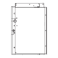
2.3.4 Fitting the installation plate
Fit the Installation Plate and drill holes in the wall
according to the wall structure and corresponding
mounting points on the installation plate.
1. Fit the installation plate horizontally on
structural parts of the wall with spaces around the
installation plate (Detailed on page 3 as
applicable).
2. If the wall is made of brick, concrete or the like,
drill eight (8) 5mm diameter holes in the wall.
Insert Plastic Expansion Sheath for appropriate
mounting screws.
3. Fit the installation plate on the wall with eight (8)
type “A” screws.
2.3.5 Drill a hole in the wall
1. Determine hole positions according to the
diagram detailed on page 3 as applicable. Drill
one (1) hole (φ85mm for those models need
φ65mm pipe hole or φ115mm for models need
φ95mm pipe hole) slanting slightly to outdoor
 Loading...