Do you have a question about the Midland 13-510 and is the answer not in the manual?
Lists various physical components for the transceiver casing.
Lists part numbers for inductors used in the unit.
Lists integrated circuits, transistors, and diodes with part numbers.
Lists other miscellaneous components like crystals and switches.
Lists specific crystal part numbers and their frequencies.
Lists part numbers for various switches and control components.
Diagrams showing pin configurations and connections for FETs and transistors.
Diagrams showing pin configurations and connections for integrated circuits.
Voltage readings for MOS-FETs across different gate and drain conditions.
Voltage readings for bipolar transistors and J-FETs under various operating conditions.
Table showing binary coded decimal values for channel selection.
Lists necessary equipment for transmitter alignment.
Lists necessary equipment for receiver alignment.
Initial setup steps for receiver alignment procedures.
General notes on alignment procedures and factory settings.
Equipment required and setup for PLL circuit alignment.
Description of RF, IF, and AF stages in the receiver path.
Description of Tx Driver Stage and Final Unit in the transmitter path.
Explains Local, Counter, VCO, Display, and Power Supply circuits.
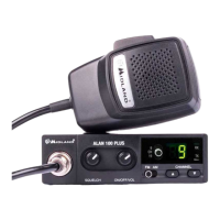
Connecting microphone, antenna, and power source before initial operation.
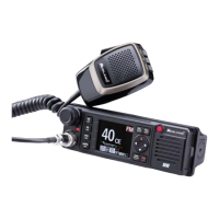
Powering on, adjusting volume, and setting frequency selectors for desired operation.
Adjusting volume, squelch, and S meter for optimal reception of signals.
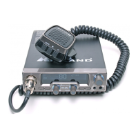
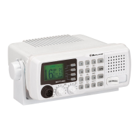
Explains front panel controls like Power, Volume, Squelch, Switches, and Meters.
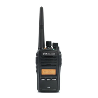
Unpacking the transceiver and checking for shipping damage.
Selecting a suitable location for the transceiver in a vehicle or base station.
Details on power source, voltage, and current requirements for operation.
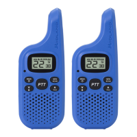
| Frequency Range | 462.5500 - 467.7250 MHz |
|---|---|
| Channels | 22 |
| Dimensions | 2.4" x 1.3" x 6.2" |
| Weight | 0.44 lbs |
| Weather Alerts | Yes |
| Power Output | 0.5 - 5 Watts |
| Antenna Connector | N/A (Integrated Antenna) |