EasyManua.ls Logo

Midland ALAN-42 DS - User Manual

Midland ALAN-42 DS
11 pages
Print Icon
To Next Page IconTo Next Page
Loading...
Adjustment Procedures for the ALAN-42 DS
1.Band setting for the production mode.
1).Turn off the radio.
2).Make Link for production mode as below.
Link S1 S2 S3 S4 Results
13 1 1 1 1 Production Mode For factory
3).Press the SCAN + AM/FM key and hold.
4).Turn on the radio.
5).The radio go to production mode. At this time the LCD display” Pd” display on the LCD, and go to Channel 1.
6). Turn off the radio.
7). Make Link as below to shipment for the default band.
Link S1 S2 S3 S4 Results
1 0 0 0 0 I, I2, d4, EU, EC, E, F, PL, UK Default band
8). Turn on the radio to adjustment.
Even if link to default band, keep the production mode until factory reset.
1-1. Table of Link.
Link S1 S2 S3 S4 Results
1 0 0 0 0 I, I2, d4, EU, EC, E, F, PL, UK Default band
2 0 0 0 1 I, I2, d4, EU, EC, E, F, PL, UK, PX
3 0 0 1 0 I, I2, d4, EU, EC, E, F, PL, UK, RU
4 0 0 1 1 I, I2, d4, EU, EC, E, F, PL, UK, PX, RU
5 0 1 0 0 Only KSA
6 0 1 0 1 Only EC
7 0 1 1 0 AU, AM
8 0 1 1 1 I, I2, d4, EU, EC, E, F, PL, UK, PX, RU, SW, AU, NZ
9 1 0 0 0 Only RU
10 1 1 0 0 RU, PC
11 1 1 0 1 Only E
12 1 1 1 0 Only NZ
13 1 1 1 1 Production Mode For factory
"0" = closed, "1" = open
Question and Answer IconNeed help?

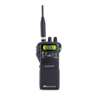
Do you have a question about the Midland ALAN-42 DS and is the answer not in the manual?

Summary

Band Setting and Production Mode

Adjustment Procedures Overview

Adjustment Location Diagrams

VCO Adjustments

VCO Lock Voltage Adjustment

Procedure and parameters for adjusting VCO Lock Voltage.

Transmitter Adjustments

Output Power Adjustments

Adjusting transmitter output power at 4W and 1W levels.

Harmonics Adjustment

Procedure for adjusting harmonics for transmitter output.

Frequency Adjustments

Adjusting transmitter frequency for standard and UK bands.

AM Modulation Adjustments

Adjusting AM modulation for transmitter output at 4W and 1W.

FM Deviation Adjustment

Adjusting FM maximum deviation for transmitter output.

Signal Meter Adjustments

Adjusting signal meter readings for transmitter output at 4W and 1W.

Receiver Adjustments

Factory Reset Procedure

Overview

This document outlines the adjustment and assembly procedures for the ALAN-42 DS device, covering band settings, frequency adjustments, transmitter and receiver adjustments, factory reset, and assembly notices.

Band Setting for Production Mode

The device features a production mode that allows for specific band configurations. To enter this mode, first ensure the radio is turned off. A specific link configuration (Link 13: S1=1, S2=1, S3=1, S4=1) must be established, which sets the device to "Production Mode." Once the link is made, press and hold the "SCAN + AM/FM" key, then turn on the radio. The device will display "Pd" on the LCD and go to Channel 1, indicating it is in production mode. After adjustments, the radio should be turned off. For shipment, the device is configured to a default band by setting Link 1 (S1=0, S2=0, S3=0, S4=0), which enables various regions and features (I, I2, d4, EU, EC, E, F, PL, UK). Even after setting the default band, the production mode is maintained until a factory reset.

The device supports multiple link configurations, each enabling different regional settings and features. For instance:

  • Link 1 (0,0,0,0): Default band for I, I2, d4, EU, EC, E, F, PL, UK.
  • Link 2 (0,0,0,1): Extends Link 1 with PX.
  • Link 3 (0,0,1,0): Extends Link 1 with RU.
  • Link 4 (0,0,1,1): Extends Link 1 with PX, RU.
  • Link 5 (0,1,0,0): Only KSA.
  • Link 6 (0,1,0,1): Only EC.
  • Link 7 (0,1,1,0): AU, AM.
  • Link 8 (0,1,1,1): A comprehensive setting including I, I2, d4, EU, EC, E, F, PL, UK, PX, RU, SW, AU, NZ.
  • Link 9 (1,0,0,0): Only RU.
  • Link 10 (1,1,0,0): RU, PC.
  • Link 11 (1,1,0,1): Only E.
  • Link 12 (1,1,1,0): Only NZ.
  • Link 13 (1,1,1,1): Production Mode.

The "0" indicates a closed link, and "1" indicates an open link.

For the Romanian market, a specific link (R852) is used to disable the power save function and change the backlight function. To enable this for Romania, R852 must be installed with an OR or solder short. The location of R852 is clearly marked on the circuit diagram.

Adjustment Procedures

The device requires several adjustments during production to ensure optimal performance.

Frequency Table for Production Mode

The device operates across various frequencies depending on the selected channel and display mode. For example:

  • Channels 1-3: 26.965 MHz, 26.975 MHz, 26.985 MHz.
  • Channels 19-21: 27.185 MHz, 27.205 MHz, 27.215 MHz.
  • Channels 38-40: 27.385 MHz, 27.395 MHz, 27.405 MHz.
  • Channels 41, 60, 80: 26.565 MHz, 26.755 MHz, 26.955 MHz.
  • "u" channels (1u, 20u, 40u): 27.60125 MHz, 27.79125 MHz, 27.99125 MHz.
  • "A" channels (1A, 2A, 3A): 25.615 MHz, 25.625 MHz, 25.635 MHz.
  • "L" channels (38L, 39L, 40L): 30.085 MHz, 30.095 MHz, 30.105 MHz.
  • Channel 1E (27.415 MHz): Used specifically for VCO Adjustment.

Adjustment Location

Key adjustment points on the circuit board include:

  • RV101, TC501: Likely for receiver or general tuning.
  • RV501: Potentially for squelch or other receiver parameters.
  • RV102, RV201, RV901, RV203, RV202: These are variable resistors or potentiometers used for fine-tuning various aspects of the device.
  • TC502: A trimmer capacitor, often used for frequency or filter adjustments.
  • L212, L211, L210, L207, L206: Inductors, likely for filtering or impedance matching in RF circuits.
  • TP501: A test point for measurement.

VCO Adjustments

The Voltage Controlled Oscillator (VCO) requires precise adjustment.

  • VCO Lock Voltage: To adjust this, select Channel 1E (27.415 MHz) and set the device to RX mode. The target voltage is 1.0V ± 0.1V, measured at test point TP501, and adjusted using TC502.

Transmitter Adjustments

Several parameters of the transmitter need to be adjusted:

  • Output Power (4W): Select Channel 41 (26.565 MHz), enable high power, select FM mode, and press the PTT key. The output power should follow specifications and is adjusted via RV202. Checks are also performed on Channels 40, 1, 40U, 1A, and 40L.
  • Harmonics: With the same settings as output power, harmonics should follow specifications. L211 and L212 are adjusted (L212 for shifting up, L210 for shifting down) to minimize harmonics. Checks are also performed on Channels 40 and 40U.
  • Output Power (1W): Select Channel 1 (26.965 MHz), enable low power, select FM mode, and press the PTT key. The output power should follow specifications. This is a check-only adjustment.
  • Frequency: Select Channel 1 (26.965 MHz), enable high power, select FM mode, and press the PTT key. The frequency should follow specifications and is adjusted via TC501.
  • Frequency (UK band): Select Channel 1U (27.60125 MHz), enable high power, and press the PTT key. This is a check-only adjustment for UK band frequency.
  • AM Modulation (4W): Select Channel 1 (26.965 MHz), enable high power, select AM mode, and press the PTT key. The AM modulation should follow specifications and is adjusted via RV203.
  • AM Modulation (1W): Select Channel 1 (26.965 MHz), enable low power, select AM mode, and press the PTT key. This is a check-only adjustment for low power AM modulation.
  • FM max Deviation: Select Channel 41 (26.565 MHz), enable high power, select FM mode, and press the PTT key. The FM deviation should be 1.7 KHz (Follow Spec) and is adjusted via RV501. Checks are also performed on Channels 1, 40, and 40U.
  • Signal Meter (4W): Select Channel 1 (26.965 MHz), enable high power, select FM mode, and press the PTT key. The signal meter should display 5 bars (4W) and is adjusted via RV201.
  • Signal Meter (1W): Select Channel 1 (26.965 MHz), enable low power, select FM mode, and press the PTT key. The signal meter should display 2 bars (1W). This is a check-only adjustment.

Receiver Adjustments

The receiver also requires several adjustments:

  • AM Max Audio and Distortion: Select Channel 20 (27.205 MHz), select AM mode, and set the SG level to -47dBm. The audio output and distortion should follow specifications. This is a check-only adjustment.
  • AM Sensitivity: Select Channel 20 (27.205 MHz), select AM mode, and set the SG level to -107dBm. The AM sensitivity should follow specifications. Checks are also performed on Channels 1 and 40. This is a check-only adjustment.
  • FM Max Audio and Distortion: Select Channel 20 (27.205 MHz), select FM mode, and set the SG level to -47dBm. The audio output and distortion should follow specifications. This is a check-only adjustment.
  • FM Sensitivity: Select Channel 20 (27.205 MHz), select FM mode, and set the SG level to -107dBm. The FM sensitivity should follow specifications. Checks are also performed on Channels 1, 40, 41, 1U, 40U, 1A, and 40L. This is a check-only adjustment.
  • Tight Squelch: Select Channel 20 (27.205 MHz), select FM mode, and set the SG level to -47dBm. The tight squelch should follow specifications and is adjusted via RV101.
  • Auto Squelch: Select Channel 20 (27.205 MHz), select AM mode, and set the SG level depending on sensitivity. The auto squelch should follow specifications and is adjusted via RV901.
  • Signal Meter: Select Channel 20 (27.205 MHz), select FM mode, and set the SG level to -67dBm. The signal meter should follow specifications and is adjusted via RV102.
  • NB (Noise Blank): Select Channel 20 (27.205 MHz), select AM mode, and enable NB by pressing the SCAN key for a long duration. The device will display a blanking AM/FM icon on the LCD. Set the SG level to -101dBm. Then disable NB by pressing the SCAN key for a long duration. This is a check-only adjustment.

Factory Reset before Shipment

Before shipment, the ALAN-42 DS must undergo a factory reset. This process ensures the device is in its default state.

  1. Turn off the radio.
  2. Set the default link (Link 1: S1=0, S2=0, S3=0, S4=0), which enables I, I2, d, d2, d3, d4, EU, EC, E, F, PL, UK.
  3. Press and hold the "SCAN + EMG" key.
  4. Turn on the radio.
  5. The LCD will display "EC" and "1", indicating a successful factory reset.

Band Selection

The device allows for manual band selection:

  1. Turn off the radio.
  2. Press and hold the "SCAN + AM/FM" key.
  3. Turn on the radio.
  4. Use the Up and Down keys to select the desired band.
  5. Press the "AM/FM" key to confirm the selection.

Assemble Notice

During assembly, specific attention is required for certain soldering and grounding points to ensure proper device functionality and to avoid issues like TX O.S.C (Transmitter Oscillation) and TX harmonics.

  1. VCO Can Soldering Point: To prevent TX O.S.C when operating at high power, the VCO can must be properly soldered at the designated points.
  2. Main Body to PCB Ground Soldering: The main body of the device needs to be soldered to the PCB ground. Additionally, a shield plate should be added to resolve TX harmonics. This ensures proper grounding and electromagnetic shielding.
  3. Main Body to Ground Soldering for ACP in AM with DC Car Adaptor: For optimal performance when using a DC car adaptor in AM mode, the main body must be soldered to the ground. This connection is crucial for the ACP (Automatic Channel Processing) function.
  4. Main Body to DC Ground Terminal Soldering for ACP in AM with DC Car Adaptor: Similarly, the main body needs to be soldered to the DC ground terminal when using a DC car adaptor in AM mode for ACP functionality.
  5. Assemble DC Car Adaptor for ACP in AM: The DC car adaptor itself needs to be properly assembled, with attention to its internal connections, to ensure reliable ACP operation in AM mode.

These detailed procedures and notices ensure the ALAN-42 DS device meets its performance specifications and operates reliably across various configurations and environments.

Midland ALAN-42 DS Specifications

General IconGeneral
Frequency Range26.965 - 27.405 MHz
Channels40
Operating ModeAM/FM
Antenna Impedance50 Ohms
Output Power4W