Technical Information
79
G 600/G 800
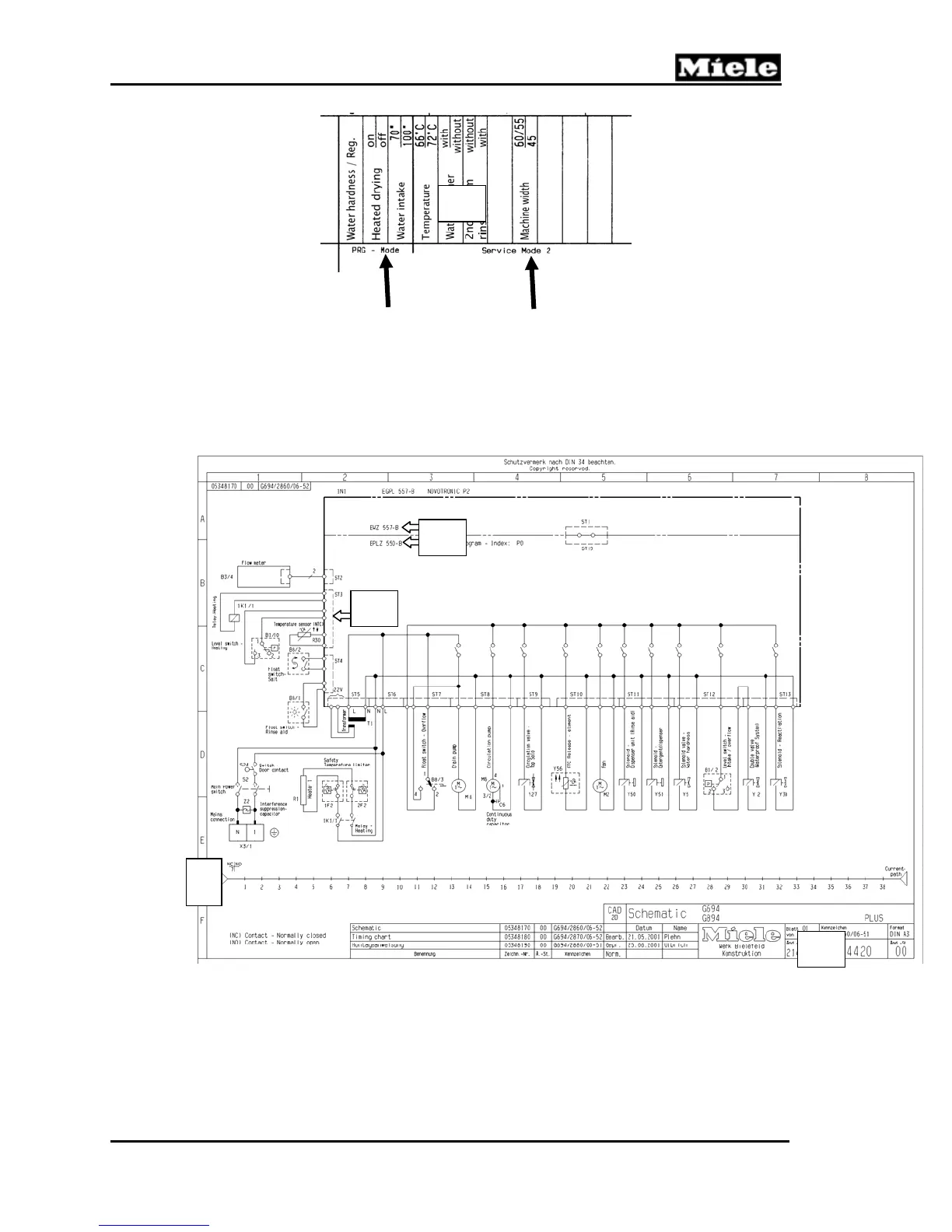
6.5 Wiring Diagrams – General Information
1
Electronic assembly (circuit boards)
2
Molex plug connectors (framed by dotted lines)
3 “Current path”; used to identify the location of the component along a numbered line.
(Example: Water inlet valve Y2 is positioned at current path 22.)
4
Wiring diagram number and applicable model number(s)
G
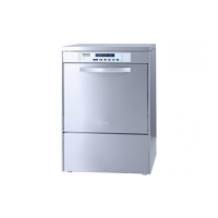
Programming mode
functions/options
Service mode 2
functions/options
1
2
3
4
 Loading...