Do you have a question about the Miele H 408 BM Series and is the answer not in the manual?
General safety guidelines and potential hazards.
Procedure to safely discharge the high-voltage capacitor before service.
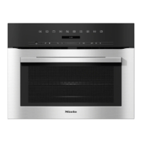
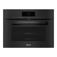
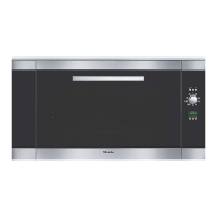
General overview of the appliance components.
Description of the appliance's control interface and buttons.
Steps for installing the appliance into a cabinet.
Procedures for removing door lock components and adjusting door switches.
Technical specifications for air duct and magnetron components.
Steps to remove the front air duct for specific machine serial numbers.
Technical specifications for convection fan and heater elements.
Procedures for removing the fan impeller and convection fan assembly.
Explanation of the Navitronic touch display's operation and features.
Identification of connectors on the power electronic module for different models.
Detailed technical data on appliance dimensions, capacity, and features.
Technical details of the control panel, including display and input methods.
Technical data on operating modes, safety features, and power connection requirements.
Visual diagram identifying major appliance components.
Diagrams showing electrical component placement for different models.
Detailed diagram of the control panel with labeled touchpads and display.
Diagram and list of electrical components for the H 4080 BM model.
Diagram and list of electrical components for H 4082 BM and later models.
Exploded view of casing and door lock components.
Steps for installing the appliance into a cabinet.
Initial setup and programming before first use.
Procedure for safely removing the appliance from its installed cabinet.
Steps for removing outer side covers and internal side panels.
Procedure for removing the door lock torsion spring.
Steps for removing the door latch mechanism.
Procedure for removing the main door lock assembly.
How to adjust the door safety switches for proper operation.
Procedure for testing and adjusting door safety switches.
Procedure for testing and adjusting the right safety switch.
Diagram of air duct and magnetron components.
Technical specifications for cooling fan, magnetron, and high-voltage components.
Explanation of air and vapor flow paths within the appliance.
Explanation of the fan cooldown function.
Explanation of microwave energy generation and distribution.
Diagram of magnetron, transformer, capacitor, and diodes.
Steps to remove the front air duct for specific machine serial numbers.
Procedure to remove rear air duct and cooling fan for specific serial numbers.
Steps for removing air duct on later machine models.
Detailed steps for removing the air duct assembly.
Procedures for removing the release element component.
Steps to remove the cooling fan for specific serial numbers.
Procedure to remove the cooling fan on later machine models.
Method for testing the magnetron filament's resistance.
Procedure to test the magnetron's functionality and resistance.
Steps to remove the magnetron component.
Procedure for removing the high-voltage capacitor.
Procedure to test the microwave output power using water and a thermometer.
Procedure to test the high-voltage transformer's resistance at specific points.
Steps to remove the high-voltage transformer.
Procedure to test the capacitance and resistance of the high-voltage capacitor.
Procedure to check the high-voltage capacitor's resistance to ground.
Procedure to test the V1 diode using a battery and voltmeter.
Procedure to test the protective diode V6's resistance.
Diagnostic procedure to troubleshoot and isolate issues with microwave function.
Procedure to test door switches 1F6 and 2F6 for proper electrical supply and continuity.
Procedure to test door switches 3F6 and 4F6 for proper electrical supply and continuity.
Exploded view of the oven door assembly.
Procedure for removing and replacing the oven door seal.
Steps for removing the outer and middle glass panes of the oven door.
Procedures for removing the door handle and inner pane.
Steps for removing the oven door complete with hinges.
Diagram of components related to the oven cavity and wave distribution system.
Technical specifications for the wave distributor motor and oven cavity light.
Procedure for removing and servicing the wave distributor motor.
Procedure for removing and replacing the oven's halogen lamp.
Procedure for measuring the oven cavity temperature under specific conditions.
Diagram of convection fan and heater elements.
Technical specifications for convection fan, heater elements, and thermostats.
Explanation of safety cutoff functions and heater element switching sequences.
Diagrams illustrating heater element activation in various operating modes.
Procedures for removing the fan impeller.
Procedure for removing the convection fan assembly.
Steps for removing the convection heater element.
Procedures for removing convection thermostat and temperature sensor.
Steps for removing the broil heater element.
Diagram of control panel and associated electrical system components.
Explanation of the Navitronic touch display's design, operation, and programming.
Explanation of the touch display's operating principle.
Explanation of the appliance's optical interface for diagnostics.
Identification and pin assignment of connectors on the EPL power electronic module for H 4080 BM.
Detailed pinout for the EPL power electronic module connectors.
Identification of connectors on the ELP power electronic module for H 4082/4/6/8 BM.
Detailed pinout for the ELP power electronic module connectors.
Summary of fault codes, descriptions, and initial causes/remedies.
Detailed diagnosis for fault codes F05 (temp sensor short) and F06 (temp sensor open).
Diagnosis for fault code F44 (interface defective).
Diagnosis for fault codes F54 (roast probe short) and F55 (safety cutoff).
Diagnosis for fault code F60 (power electronic temp high).
Troubleshooting for display dimming and brightness issues.
Troubleshooting for oven light behavior and cooking process not starting.
Troubleshooting for buzzer tone, system lock activation, and weight unit settings.
Troubleshooting for temperature format and fuse tripping issues.
Guidance on fuse replacement and troubleshooting roast probe values.
Diagnosis and remedies for safety relay trips due to power/control electronic faults or high temperature.
Procedure to access the programming mode for H 4080 BM models.
Overview of programmable settings like Language, Clock, and Temperature.
Procedure to access programming mode for H 4082/4/6/8 BM models.
Detailed table of programmable settings for H 4082/4/6/8 BM models.
Instructions for saving, quitting, or discarding changes in programming mode.
Procedure to access the service mode for H 4080 BM models.
Overview of service mode functions including index, fault index, and function tests.
Procedure to access service mode for H 4082/4/6/8 BM models.
Details on sensor tests and running time display within the service mode.
Procedure to access and view stored fault codes in the appliance's memory.
Instructions for clearing stored fault codes from the appliance's memory.
Steps for removing the fascia panel, including screw types and disconnection of electronics.
Procedure for removing the fascia panel along with its support plate.
Steps for removing the support plate assembly.
Procedure for disconnecting and removing the power electronic board.
Explanation of cooling fan operation and behavior in Miele ovens.
Solution for control panel fogging issue, involving installing a seal.
Information on replacing the broil element, including new conversion kit parts.
Information on replacing the optional waveguide cover and available part numbers.